HCD-GN1300D
22
SECTION 5
ELECTRICAL ADJUSTMENTS
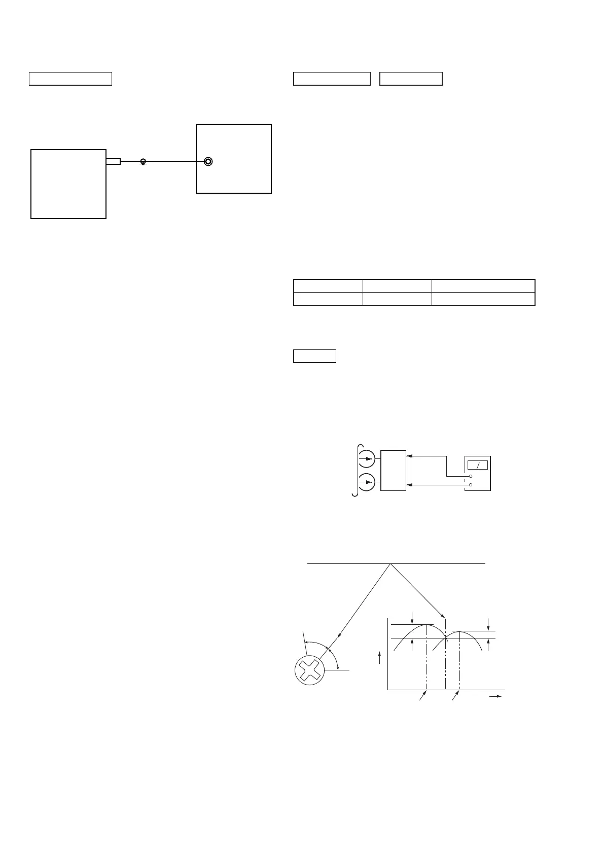
[FM Tune Level Check]
Procedure:
1. Turn the power on.
2. Input the following signal from Signal Generator to FM
antenna input directly.
* Carrier Freq : A = 87.5 MHz, B = 98 MHz, C = 108 MHz
Deviation : 75 kHz
Modulation : 1 kHz
ANT input : 35 dBu (EMF)
Note: Please use 75 ohm “coaxial cable” to connect SG and the set. You
cannot use video cable for checking.
Please use SG whose output impedance is 75 ohm.
3. Set to FM tuner function and tune A, B and C signals.
4. Confi rm “TUNED” is lit on the display for A, B and C
signals.
The mark of “TUNED” means “The selected station signal is
received in good condition.”
TUNER SECTION
FM signal generator
OUT (75 7)
SET
DECK SECTION
Tape Signal Used for
P-4-A100 10 kHz, –10 dB Azimuth Adjustment
0 dB=0.775V
1. Demagnetize the record/playback head with a head demagne-
tizer.
2. Do not use a magnetized screwdriver for the adjustments.
3. After the adjustments, apply suitable locking compound to the
parts adjusted.
4. The adjustments should be performed with the rated power
supply voltage unless otherwise noted.
5. The adjustments should be performed in the order given in this
service manual. (As a general rule, playback circuit adjustment
should be completed before performing recording circuit ad-
justment.)
6. The adjustments should be performed for both L-CH and
RCH.
7. Switches and controls should be set as follows unless other-
wise specifi ed.
• Test Tape
RECORD/PLAYBACK HEAD AZIMUTH ADJUSTMENT
Procedure:
1. Mode: Playback
set
Audio Out Jack
at Back Panel
(White-L-CH)
(Red-R-CH)
Chassis GND
+
–
level meter
test tape
P-4-A100
(10 kHz, –10 dB)
2. Turn the adjustment screw and check output peaks. If the
peaks do not match for L-CH and R-CH, turn the adjustment
screw so that outouts match within 1dB of peak.
DECK
L-CH
peak
Output
level
within
1dB
within
1dB
Screw
position
R-CH
peak
R-CH
peak
L-CH
peak
Screw
position