28
HCD-GNV99D/GNV111D
DVD SECTION
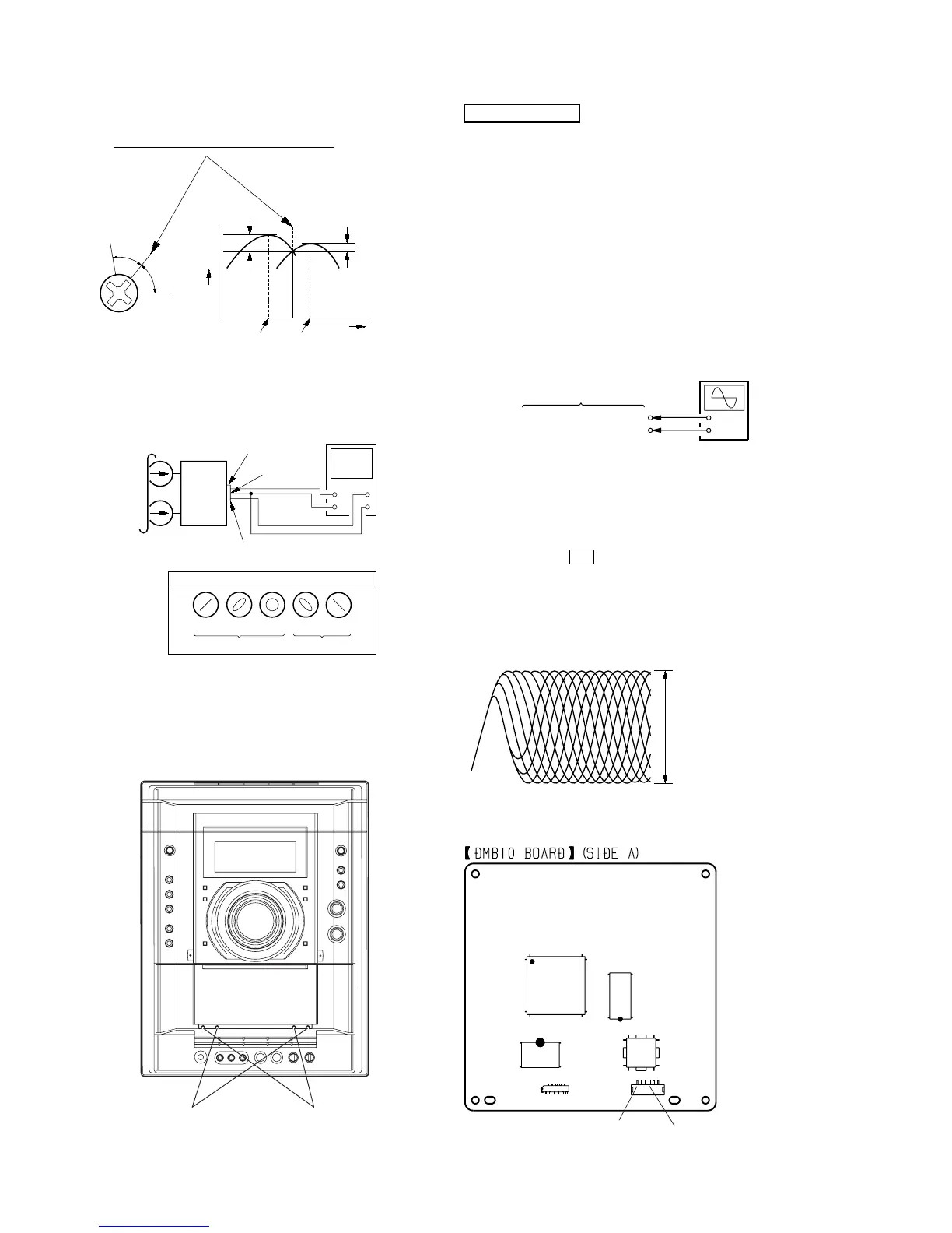
AUTO SERVO ADJUSTMENT
After parts related to the servo circuit (RF amplifier , DSP (IC102),
motor driver (IC201), EEPROM (IC103) so on) are replaced, re-
adjusting the servo circuit is necessary.
[TEST DISC LIST]
Use the following test disc on test mode.
TDV-520CSO (DVD-SL): PART No. J-2501-236-A
LUV-P01 (CD): PART No. 4-999-032-01
TDV-540C (DVD-DL): PART No. J-2501-235-A
Note: Do not use exiting test disc for DVD.
[RFMON Level Check]
Connection:
Procedure:
1. Connect an oscilloscope to CN105 pin 6 (RFMON) and
CN105 pin 3 (GND) on the DMB10 board.
2. Turn the power on.
3. Set the test disc (DVD: TDV-520CSO, CD: LUV-P01) on the
tray and press H button to playback.
4. Confirm that oscilloscope waveform is clear and check
RFMON signal level is correct or not.
Note: A clear RFMON signal waveform means that the shape “◊” can be
clearly distinguished at the center of the waveform.
Checking Location: DMB10 board (Side A)
+
–
CN105 pin
6
(RFMON)
CN105 pin
3
(GND)
oscilloscope
DMB10 board
VOLT/DIV: 200 mV
TIME/DIV: 500 ns
RFMON signal waveform
level: 0.8 ± 0.2 Vp-p (DVD)
0.8 ± 0.2 Vp-p (CD)
IC102
IC101
IC104
IC201
CN105
CN106
CN105 pin 3 (GND)
CN105 pin 6 (RFMON)
1
6
2. Turn the adjustment screw and check output peaks. If the peaks
do not match for L-CH and R-CH, turn the adjustment screw
so that outputs match within 1dB of peak.
3. Mode: Playback
4. After the adjustments, apply suitable locking compound to
the pats adjusted.
Adjustment Location: Playback Head (Deck A).
Record/Playback/Erase Head (Deck B).
Screw
position
L-CH
peak
within
1dB
Output
level
L-CH
peak
R-CH
peak
within
1dB
Screw
position
R-CH
peak
MAIN
board
CN510
set
test tape
P-4-A100
(10 kHz, –10 dB)
pin
3
oscilloscop