HCD-SX7/SX7B
25
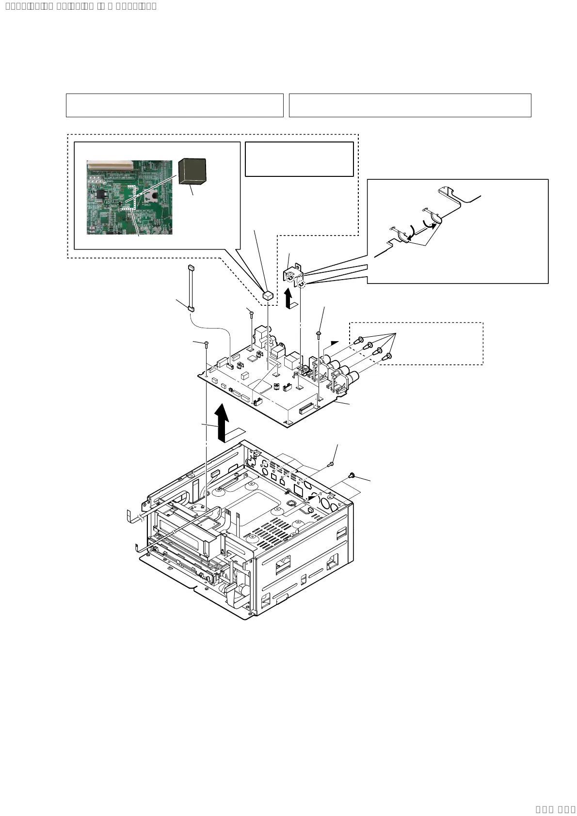
2-19. MAIN BOARD-2
(AEP, RU, UK, E32, SP,
AR, TH, IDN, AUS)
A
A
– MAIN board bottom view –
3 five screws
(BV3)
(L=6 mm)
7 card WLAN/BT combo
cable connector
(CN606)
4 two screws
(TAPTITE 3 u 8)
3 screw
(BV3)
(L=6 mm)
2 four screws
(BV/ring)
(L=8 mm)
1 two ornament screws
8 bracket (LAN)
9 radiation sheet (MTK)
qa MAIN board
0 four canoe clips
5 Remove the MAIN board block
in the direction of the arrow.
6 Bend two legs of bracket (LAN)
in the direction of the arrow.
3DVWLQJSRVLWLRQRIUDGLDWLRQVKHHW07.
guide line
radiation sheet
(MTK)
Note 3:
Radiation sheet (MTK)
is deleted from the
midway of production.
Note 1: When the MAIN board is replaced, refer to “CHECKING
OF NETWORK CONNECTION” on page 5.
Note 2: When replacing the MAIN board of AEP and UK models, be sure
to refer to “TYPE OF AEP AND UK MODELS” on page 6.
Ver. 1.2
SYSSET
2020/02/2722:53:44(GMT+09:00)


 To Next Page