64
4-26. SW-1753 Board
Preparation
1. Remove the outside assembly. (Refer to "4-4. Outside Assembly")
2. Remove the inside assembly. (Refer to "4-5. Inside Assembly")
3. Remove the rear panel assembly. (Refer to "4-18. Rear Panel Assembly")
4. Remove the CN-4066 board. (Refer to "4-25. CN-4066 Board")
5. Remove the rear harness protection sheet. (Refer to steps 1 and 2 in "4-19. DC Fan")
Procedure
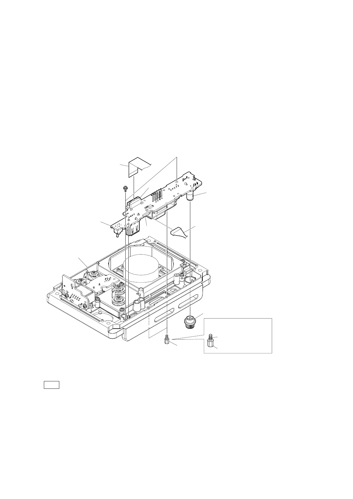
1. Disconnect the flexible flat cable from the connector (CN002) on the SW-1753 board.
2. Remove the two hexagonal screws.
3. Remove the encoder knob.
4. Remove the two screws, and then remove the SW-1753 board.
5. Disconnect the harness from the connector (CN001) on the SW-1753 board.
• When attaching the two hexagonal screws, apply the locking compound.
• When attaching the encoder knob, pay attention to the direction of the encoder knob and the D cut of the encoder. If the
direction is not aligned, the encoder knob may be damaged.
PSW
2 x 5
SW-1753 board
Rear panel assembly
Flexible flat cable
CN002
Harness
CN001
Encoder knob
Hexagonal
screws
Hexagonal screw
Locking compound 1401B
(Size of a grain of rice)
Encoder
Locking compound
application area
This figure shows HDC-P50.



 To Next Page