12
CE model: For Europe and South Asia
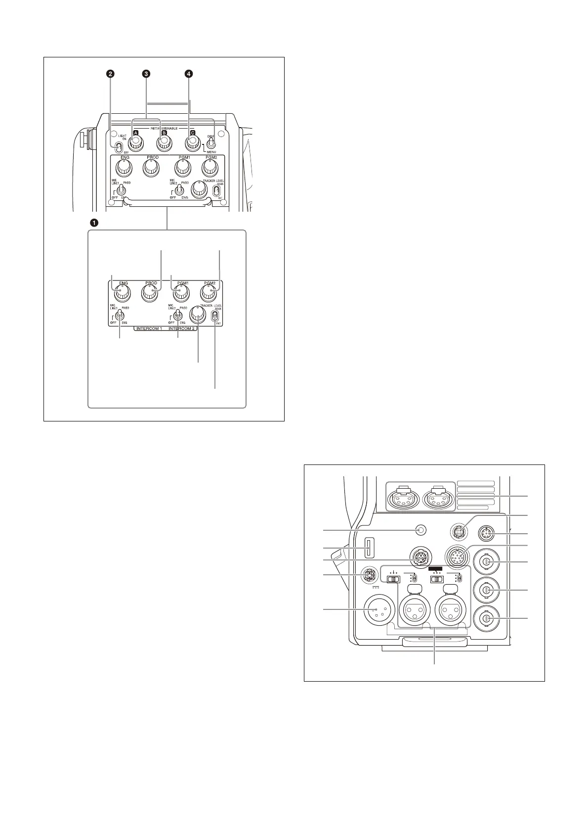
a INTERCOM 1 and INTERCOM 2 controls and switches
The reception level controls are common to intercom 1 and
intercom 2. The talk lines can be set independently for
intercom 1 and intercom 2.
ENG (engineer line) control
Adjust the intercom audio listening level of the engineer
line.
PROD (producer line) control
Adjust the intercom audio listening level of the producer
line.
PGM1 (program 1) control
Adjust the audio listening level of program 1, and program
3 (when PGM3 VOLUME LINK is set to PGM1).
PGM2 (program 2) control
Adjust the audio listening level of program 2, and program
3 (when PGM3 VOLUME LINK is set to PGM2).
MIC LINE1 (intercom microphone line 1) switch
Select the talk line for intercom 1.
PROD: To talk over the producer line
OFF: To turn off the headset microphone for intercom
line 1.
ENG: To talk over the engineer line
MIC LINE2 (intercom microphone line 2) switch
Select the talk line for intercom 2.
PROD: To talk over the producer line
OFF: To turn off the headset microphone for intercom
line 2.
ENG: To talk over the engineer line
TRACKER control
Adjust the intercom audio listening level at the TRACKER
connector (
page 13
) on the connector panel when using the
connector for intercom.
LEVEL switch
REAR: The intercom audio listening level is adjusted
with the controls on this panel.
FRT: The intercom audio listening level is adjusted with
the INTERCOM LEVEL control on the front of the
camera.
b LIGHT switch
Set to ON to illuminate the operation panel.
c RET/ASSIGNABLE button A, B
Press the button to switch the function assigned to the
button on the <ROTARY ENCODER ASSIGN> page on/off.
When the return function is assigned, press the button to
display the return video signal on the viewfinder screen
while the button is pressed.
Turn the button to change the assigned function setting.
When the return function is assigned, you can change the
return signal channel.
d RET/ASSIGNABLE button C / DISP/MENU switch
Press the button to switch the function assigned to the
button on the <ROTARY ENCODER ASSIGN> page on/off.
When the return function is assigned, press the button to
display the return video signal on the viewfinder screen
while the button is pressed.
Turn the button to change the assigned function setting.
When the return function is assigned, you can change the
return signal channel.
When the DISP/MENU switch is set to the MENU position to
display the MENU screen, you can perform menu
operations using RET/ASSIGNABLE button C.
Connector panel
a EARPHONE jack (4-pole mini jack)
Connect to a headset, or earphones with microphone (3-
pole/4-pole earphones), to input/output the intercom
audio signal.
For 4-pole earphones, the intercom line is linked to the
OPERATION LINK setting on the <EARPHONE> page in the
OPERATION menu.
PGM1
control
PGM2 control
TRACKER
control
LEVEL switch
MIC LINE1
switch
ENG
control
PROD control
MIC LINE2
switch
PROMPTER
TEST
OUT
LINE
+48V
OFF
MIC
SDI
MONI
AUDIO IN
CH1 CH2
/GEN
LOCK
LINE
+48V
OFF
FRONT MIC
MIC
EARPHONE
RET CTRL
DC IN 10.5-17V
DC OUT
CRANE
TRACKER
REMOTE
AES/EBU
a
b
c
d
e
f
g
h
i
j
k
l
m