24
The <FOCUS ASSIST> page is displayed.
3 Rotate the MENU SEL knob/ENTER button to align the
arrow marker (
,) to the item to be set and push on
the MENU SEL knob/ENTER button.
To use the level indicator
Setting INDICATOR to ON displays the level indicator on
the viewfinder.
You can set the display format with the menu items
below.
MODE: Set the type and position of the indicator.
LEVEL: Set the density and the response speed of the
indicator.
GAIN: Set the sensitivity of the indicator.
1)
OFFSET: Set the offset of the focus detection value.
2)
1)
Normally, the sensitivity of the indicator is automatically set
to the optimum value in conjunction with the AREA MARKER
SIZE set value. Use this setting when an optimum sensitivity
value cannot be obtained, depending on the shooting
environment.
2)
Normally, the optimum offset is automatically set in
conjunction with the AREA MARKER SIZE and MASTER GAIN
set values. Use this setting when the optimum offset cannot
be obtained, depending on the shooting environment.
To use the area marker
Setting AREA MARKER to ON displays the detection
area of the focus as a marker on the viewfinder screen.
You can set the size and position of the detection area
with the menu items below.
SIZE: The size of the detection area can be changed. (If
the area size is too large, both the subject and the
background are included in the area, making the
indicator display may easily deviate from the
subject.)
POSITION: Roughly set the position of the detection
area.
POSITION H: Finely adjust the position of the detection
area in the horizontal directions.
POSITION V: Finely adjust the position of the detection
area in the vertical directions.
4 Rotate the MENU SEL knob/ENTER button to display
the desired setting and push on the MENU SEL knob/
ENTER button.
5 To finish the adjustment, set the DISPLAY switch to
OFF to exit Menu mode.
Notes
• The level indicator and the effect area marker cannot be
displayed simultaneously, whichever you set to ON later
is preferentially displayed.
• The area marker and the aspect safety marker cannot be
displayed simultaneously, whichever you set to ON later
is preferentially displayed.
• When displaying the focus assist indicators, check that
the flange focal length has been precisely adjusted.
See “Adjusting the Flange Focal Length” on page 15 for
the flange focal length.
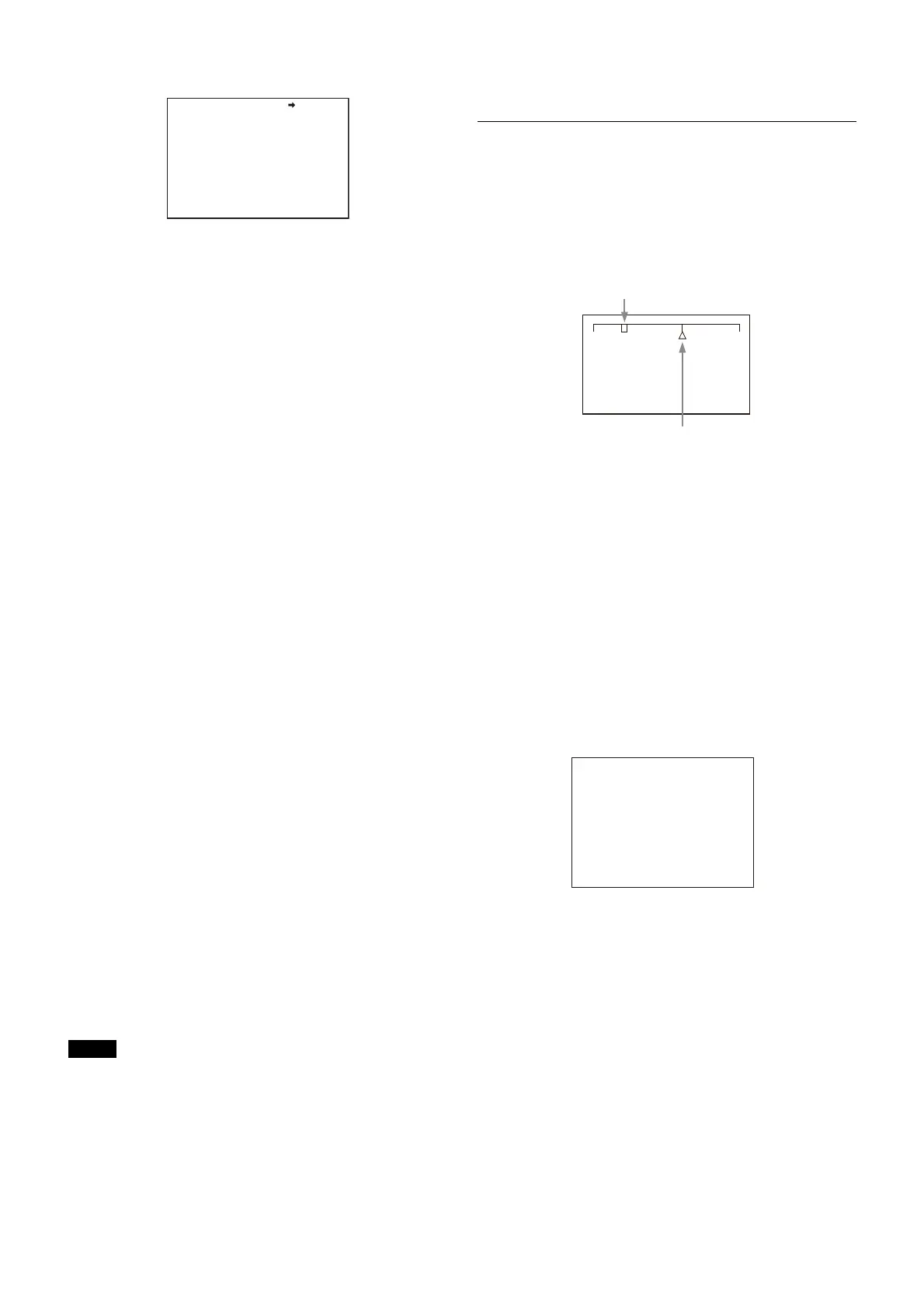
Setting the Focus Position Meter
Function
The focus position meter function allows you to graphically
display the registered focus position (marker) and the
current focus position (index) graphically on the viewfinder
screen.
You can set the focus to the registered point easily by
adjusting the focus until the index position overlaps the
marker position (adjusted state). In the adjusted state, you
can display a color frame and marker name on the
viewfinder screen.
1 Display the CONTENTS page of the OPERATION menu
(referring to steps 1 to 4 in “Adding the VF detail
signal”).
2 Turn the MENU SEL knob/ENTER button to align the
arrow marker (,) to <FOCUS POSITION METER1> or
<FOCUS POSITION METER2>, and press the MENU SEL
knob/ENTER button.
The <FOCUS POSITION METER1> page or <FOCUS
POSITION METER2> page is displayed.
3 Turn the MENU SEL knob/ENTER button to align the
arrow marker (,) to the item to be set and press the
MENU SEL knob/ENTER button.
To use the focus position meter
Setting FOCUS POSITION METER to ON displays the
focus position meter on the viewfinder screen.
You can set the display format with the <FOCUS
POSITION METER1> page items below.
NEAR LIMIT: Sets the NEAR edge of the focus position
meter.
FAR LIMIT: Sets the FAR edge of the focus position
meter.
The focus position range to display varies depending on
the NEAR LIMIT and FAR LIMIT settings. The full range is
displayed by setting NEAR LIMIT to 0 and FAR LIMIT to
999.
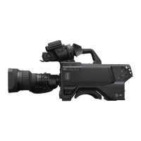
<FOCUS ASSIST> 08 TOP
INDICATOR : OFF
MODE : BOX BOTTOM
LEVEL : 3 QUICK
GAIN : 50
OFFSET : 50
AREA MARKER: ON
SIZE : MIDDLE
POSITION : CENTER
POSITION H: 50
POSITION V: 50
NEAR FAR
Current focus position (index)
Registered focus position (marker)
<FOCUS POSITION METER1>
FOCUS POSITION METER: ON
NEAR LIMIT : 100 (0~999)
FAR LIMIT : 923 (0~999)
DIRECTION : HORIZONTAL
SIZE : NORMAL
RULED LINE : ON
INDEX COLOR : WHITE
INDEX WIDTH : 1
MARKER WIDTH : 1
CURRENT FOCUS DIST :_5.7M 18.7ft
236 (0~999)
06 TOP