13
Turn the microphone function on/off using HEADSET MIC
(page 49)
in the OPERATION menu. The default setting is
OFF.
b USB connector (for connecting a USB drive)
Connect a USB drive to save or load the settings data file.
For details, see “Using a USB drive” (page 96).
c TRACKER connector (12-pin)
For external interface, such as intercom and tally.
d RET CTRL (return control) connector (6-pin)
For connection to a CAC-6 Return Video Selector.
e DC IN (DC power supply input) connector (XLR 4-pin)
Used for connection to the AC-DN10A AC Adaptor to supply
power to the camera.
f INTERCOM1 and 2 (intercom 1 and 2) connectors (XLR
5-pin)
Used for input and output of intercom audio signals if an
XLR 5-pin headset is connected.
The INTERCOM 1 connector can be used for communication
over the engineer line even when the power is off, as long
as the power LED is lit in red.
g DC OUT (DC power supply output) connector (4-pin)
To supply power to devices such as a wireless receiver
(optional) (max. 0.5 A).
h REMOTE connector (8-pin)
For connection to an RCP-3000/1000 series Remote Control
Panel, or MSU-1000/1500 Master Setup Unit.
Note
When the camera is connected to a CCU, do not connect
any remote control device, such as RCP and MSU, to this
connector.
i CRANE connector (12-pin)
For external interface, such as viewfinder and external data.
j PROMPTER/GENLOCK (prompter 1 signal output/
external gen-lock signal input) connector (BNC-type)
The PROMPTER OUT function is enabled when a camera
control unit is connected. The GENLOCK IN function is
enabled when a camera control unit is not connected.
GENLOCK IN: For input of an external gen-lock signal (VBS
or 3-level sync) during stand-alone operation.
PROMPTER: For output of the prompter 1 signal (valid only
when a camera control unit is connected). When a
camera control unit having two prompter inputs is
connected, the signal of input 1 is output from this
connector.
k TEST OUT connector (BNC-type)
To output the analog signal.
This can also output a VBS signal, HD-SYNC signal, or
SD-SYNC signal, whichever is selected in the menu.
For details on the output signals, see “Setting the Camera
Outputs” (page 26).
l SDI MONI (serial digital interface) connector (BNC-
type)
For HD-SDI or SD-SDI signal output.
For details on the output signals, see “Setting the Camera
Outputs” (page 26).
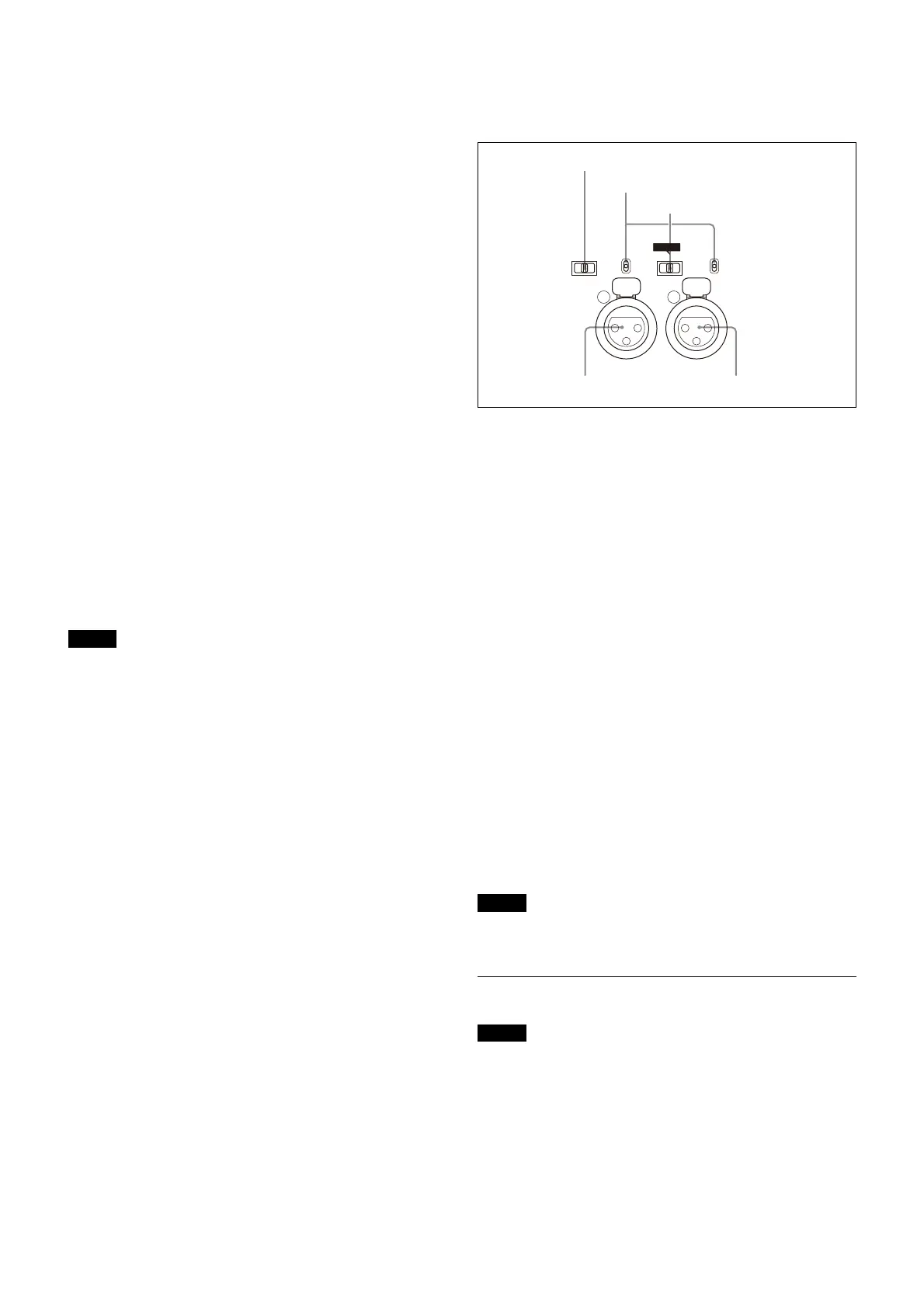
m AUDIO IN CH1 and CH2 connectors (XLR 3-pin) and
switches
Connect audio signals. An input select switch and
microphone power switch are provided for each channel.
CH1 audio input select switch
Set to the appropriate position according to the equipment
connected to the AUDIO IN CH1 connector.
LINE: When a line-level (0 dBu) signal source is
connected
FRONT MIC: When using the microphone connected to
the MIC 1 IN connector
MIC: When an external microphone is connected
CH2 audio input select switch
Set to the appropriate position according to the equipment
connected to the AUDIO IN CH2 connector.
LINE: When a line-level (0 dBu) signal source is
connected
AES/EBU: When a digital audio signal is connected
(The signal must be in synchronization with the
camera output).
MIC: When an external microphone is connected
Microphone power switches
When a microphone is connected to the corresponding
AUDIO IN connector, set whether or not to supply power to
the microphone.
+48V: To supply power at +48 V
OFF: Not to supply power
(No function has been assigned to the lowermost
position. No power is supplied to the microphone.)
Note
To supply +12 V power, contact a Sony sales representative
or Sony service representative.
Transmission Adaptor Options
Note
For safety, only a qualified technician with service training
should perform tasks inside the unit.
For details about installation, contact a Sony service or sales
representative.
HKC-FB50 UHB Fiber Transmission Adaptor
The name and function of the connectors used are
described below.
LINE
+48V
OFF
MIC
AUDIO IN
CH1 CH2
LINE
+48V
OFF
FRONT MIC
MIC
AES/EBU
CH2 audio input select switch
CH1 audio input select switch
Microphone power switches
AUDIO IN CH1 connector AUDIO IN CH2 connector