14
NETWORK TRUNK connector (RJ-45 8-pin) (see item 1 of
front left side
(page 10)
): Connects a device
connected to the CCU’s NETWORK TRUNK connector to
the network.
CCU (camera control unit) connector (see item 4 of rear
side
(page 10)
): Connect a CCU using an optical/
electrical multi cable.
SDI 1 (serial digital interface 1) connector (BNC-type) (see
item 5 of rear side
(page 10)
): For HD-SDI signal, 3G-
SDI signal, 6G-SDI signal, 12G-SDI signal, and UHD
PROMPTER signal output.
SDI 2 (serial digital interface 2) connector (BNC-type) (see
item 6 of rear side
(page 10)
): For HD-SDI signal, 3G-
SDI signal, 6G-SDI signal, and 12G SDI signal output, or
HD TRUNK and UHD TRUNK signal input.
During standalone operation, input the HD-SDI return
signal.
When RET (return) is set to 1, the return signal is
displayed in the viewfinder.
SDI 3 (serial digital interface 3) connector (BNC-type) (see
item 7 of rear side
(page 10)
): For HD prompter
signal output.
HKC-FB30 Fiber Transmission Adaptor
The name and function of the connectors used are
described below.
NETWORK TRUNK connector (RJ-45 8-pin) (see item 1 of
front left side
(page 10)
): Connects a device
connected to the CCU’s NETWORK TRUNK connector to
the network.
CCU (camera control unit) connector (see item 4 of rear
side
(page 10)
): Connect a CCU using an optical/
electrical multi cable.
SDI 1 (serial digital interface 1) connector (BNC-type) (see
item 5 of rear side
(page 10)
): For 3G-SDI signal, HD-
SDI signal, or HD PROMPTER signal output.
SDI 2 (serial digital interface 2) connector (BNC-type) (see
item 6 of rear side
(page 10)
): For 3G-SDI signal, HD-
SDI signal, or HD TRUNK signal input.
During standalone operation, input the HD-SDI return
signal.
When RET (return) is set to 1, the return signal is
displayed in the viewfinder.
PROMPTER2 (prompter 2) connector (BNC-type): For
prompter 2 signal output. Available only when
connecting a camera control unit with a prompter 2
input connector.
HKC-TR37 Triax Transmission Adaptor
The name and function of the connectors used are
described below.
CCU (camera control unit) connector (see item 4 of rear
side
(page 10)
): Connect a CCU using a triax cable.
SDI 1 (serial digital interface 1) connector (BNC-type) (see
item 5 of rear side
(page 10)
): For 3G-SDI signal or
HD-SDI signal output.
HKC-WL50 Wireless Transmission Adaptor
Connects video signals and control signals to a third-party
wireless module to support wireless transmission.
For details about supported wireless modules, contact your
Sony sales representative.
Preparations
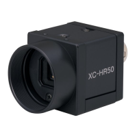
Attaching a Lens
For information on handling lenses, refer to the lens’
operation manual.
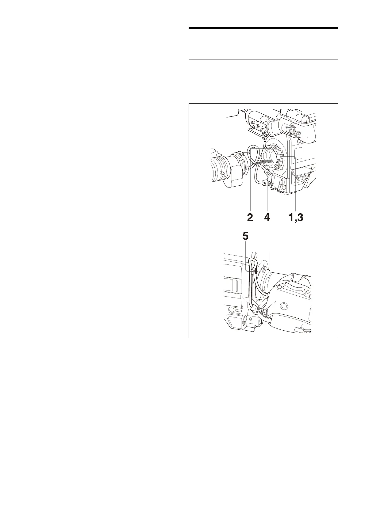
Attaching procedure
1 Push the lens fixing lever upwards and remove the
lens mount cap from the lens mount.
2 Align the lens’ alignment pin with the notch in the
upper part of the lens mount and insert the lens into
the mount.
3 While supporting the lens, push the lens fixing lever
downwards to secure the lens.
4 Connect the lens cable to the LENS connector.
5 Secure the lens cable with the cable clamp.