10
Note
When a camera control unit or a remote control device,
such as an MSU or RCP-series Remote Control Panel, is
connected, the functions of 6 to 9 are controlled from the
external control device and the controls on the camera are
disabled.
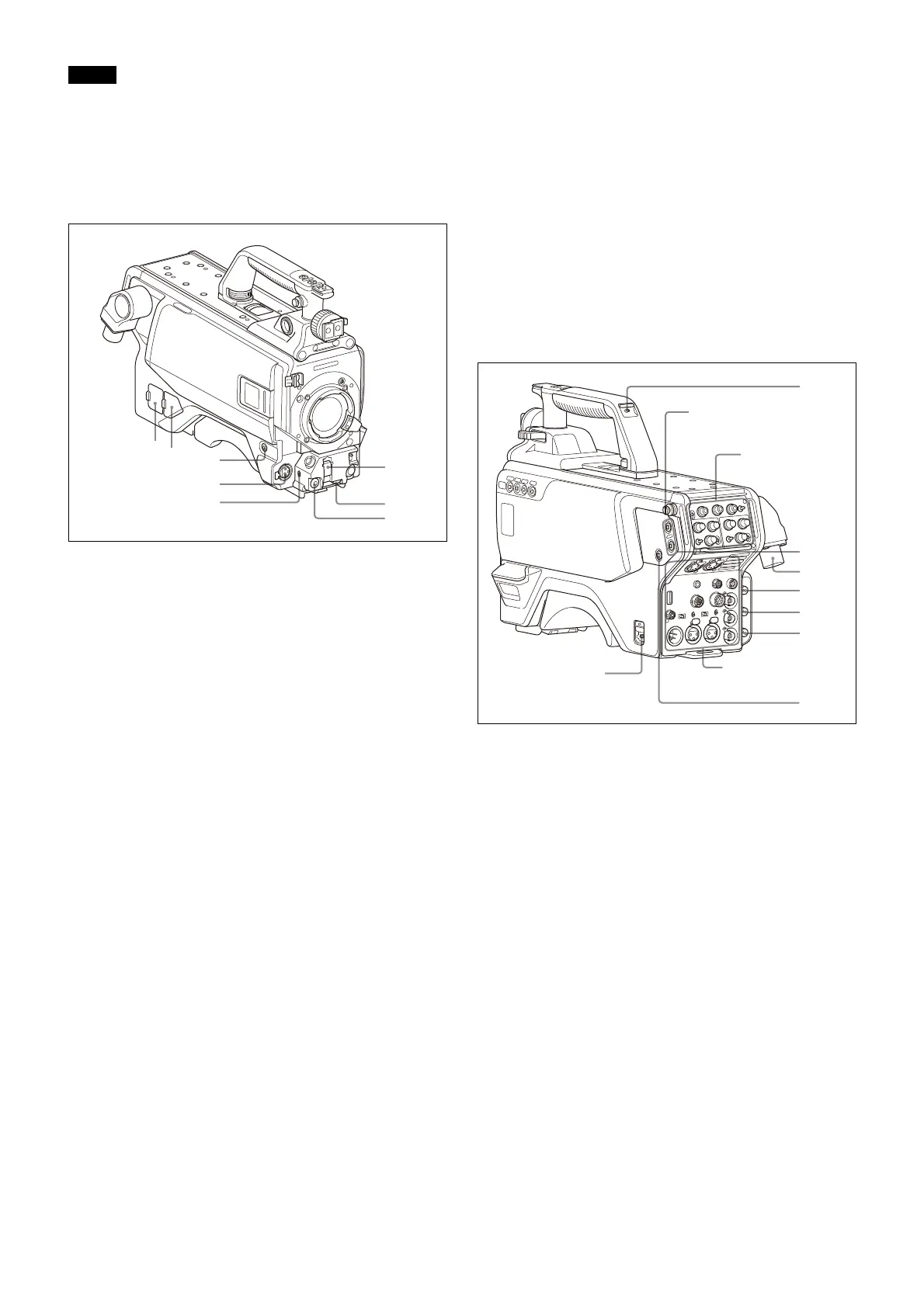
Front left
a NETWORK TRUNK connector (RJ-45 8-pin)
Connects a device connected to the CCU’s NETWORK
TRUNK connector to the network.
b DC power supply out connector (2-pin)
Supplies power to an external device up to 2.5 A.
c RET 1 (return video 1) button
The return video 1 signal from the camera control unit is
monitored on the viewfinder screen while this button is
pressed. It function the same as the RET 1 button on the
handle (
page 9
) and RET/ASSIGNABLE button A on the
operation panel on the rear of the camera (
page 11
or
12
).
You can also assign other functions to this button, using the
menu displayed on the viewfinder screen.
d MIC 1 IN (microphone 1 input) connector (XLR 3-pin)
Connect a microphone.
This connector and the AUDIO IN CH-1 connector (
page 13
)
on the operation panel on the rear of the camera are
alternately activated with the CH1 audio input select switch
(
page 13
).
e MIC (microphone) power switch
+48V: To supply power at +48 V to the connected
microphone.
OFF: Not to supply power to the connected microphone.
f SHUTTER switch
For setting the electronic shutter functions when the
camera is used in standalone status without connecting a
camera control unit.
OFF: The electronic shutter does not function.
ON: The electronic shutter is activated.
SEL: The shutter speed and shutter mode change each time
the switch is set to this position.
For details, see “Setting the Electronic Shutter” on page 22.
g INTERCOM LEVEL control
To adjust the intercom/earphone volume level.
The intercom level adjustment is enabled when the
INTERCOM 1 and 2 LEVEL/MIC switches (on the UCJ model
operation panel,
page 11
) are set to “FRONT” or the LEVEL
switch (on the CE model operation panel,
page 12
) on the
rear of the camera is set to “FRT.”
h RET 2 (return video 2) button
When this button is pressed, the picture on the viewfinder
screen changes to the return video signal selected using
RET/ASSIGNABLE button A, B, or C on the operation panel
on the rear of the camera or using the menu.
You can also assign other functions to this button, using the
menu displayed on the viewfinder screen.
Rear
a CAMERA POWER switch
CCU: Power is supplied from the camera control unit.
EXT: Power is supplied through the DC IN connector.
b Tally lamp and switch
ON: The tally lamp lights when a tally signal is input to the
connected camera control unit or a call signal is
generated in response to pressing of a CALL button.
OFF: The tally lamp is prevented from lighting.
c RET 1/2 (return video 1/2) buttons
When pressed, the picture on the viewfinder screen changes
to the return video signal selected using the operation panel
on the rear of the camera or using the menu.
You can also assign other functions to this button, using the
menu displayed on the viewfinder screen.
d CCU (camera control unit) connector
Connect a camera control unit using an optical/electrical
multi cable.
e SDI 1 (serial digital interface 1) connector (BNC-type)
HDC5500: For HD-SDI signal, 3G-SDI signal, 6G-SDI signal,
12G-SDI signal, and UHD PROMPTER signal output.
HDC3500: For 3G-SDI, HD-SDI, or HD PROMPTER signal
output.
For details on the output signals, see “Setting the Camera
Outputs” (page 26).
Operation
panel (
page 11
)
Shoulder strap fitting
post (
page 8
)
Connector panel
(
page 12
)