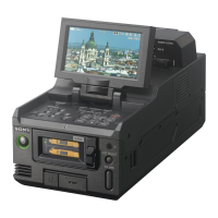
Connecting External Monitors and Camcorders
65
Connecting External Devices
To display recording/playback pictures on an
external monitor, select the output signal and use
an appropriate cable for the monitor to be
connected.
Regardless of the 3G, HD, or SD signal, the same
status information and menus that appear on the
LCD monitor can be displayed on the external
monitor. Set [SDI/HDMI/Video Out Super]
(page 51) in the [VIDEO SET] menu to [On].
When outputting SD signals in HD Mode, select
the output mode in advance using [Down
Converter] (page 51) in the [VIDEO SET] menu.
Note
When down-converted SD signals are output, images of
50P/50i/25P are output as PAL signals, images of
59.94P/59.94i/29.97P are output as NTSC signals, and
images of 23.98P are output as 2-3 pulled-down NTSC
signals.
SDI OUT 1/2 connectors (BNC type)
The following signals are output depending on
the 3G/HD/SD setting on the recorder.
• 3G SDI signals
• HD SDI signals (default setting)
• SDI signals
Set [SDI/HDMI/i.LINK I/O Select] (page 50) in
the [VIDEO SET] menu to output down-
converted SD SDI signals for monitoring, even in
HD Mode.
If an HDV or DVCAM stream is being input from
the device connected to the i.LINK connector,
you can output the input signal on the i.LINK
connector from the SDI OUT 1/2 connectors.
Use a commercially available 75-ohm coaxial
cable for connection.
Note
Support for Level A for 3G SDI signals is planned for
future updates.
HDMI OUT connector (Type A connector)
Signal output from this connector is enabled by
setting [SDI/HDMI/i.LINK I/O Select] (page 50)
in the [VIDEO SET] menu.
In HD Mode, you can select HD HDMI, SD
HDMI interlace, or SD HDMI Progressive
output.
In SD Mode, only an SD HDMI interlace signal
can be output.
Use a commercially available HDMI cable for
connection.
VIDEO OUT connector (BNC type)
By changing the setting of [SDI/HDMI/i.LINK
I/O Select] (page 50) in the [VIDEO SET] menu,
you can output HD-Y signals in HD Mode or
down-converted SD analog composite signals for
monitoring in SD Mode.
Use a commercially available BNC cable for
connection.
i.LINK connector (IEEE1394, 4-pin)
Input/output of an HDV or DVCAM stream can
be enabled by changing [SDI/HDMI/i.LINK I/O
Select] (page 50) in the [VIDEO SET] menu.
To set the input, select [i.LINK] in [Input Source
Select] (page 49) in the [VIDEO SET] menu.
A monitor or VTR that supports i.LINK can be
connected (page 68).
AUDIO OUT connector (pin jack)
Outputs the recording audio signal during
recording or standby mode, and outputs the
playback signal during playback.
By changing the setting of [AUDIO OUTPUT] >
[Output CH] in the [AUDIO SET] menu, you can
select channels 1 and 2 or channels 3 and 4 for
audio output.
Use a commercially available audio cable for
connection.
SDI IN Connector (BNC type)
The recorder supports the input of SDI signals
(3G SDI/HD SDI/SD SDI), from a camcorder or
other device for recording or output to another
device.
To set an SDI input signal, select [SDI] in [Input
Source Select] in the [VIDEO SET] menu.
Use a commercially available 75-ohm coaxial
cable for connection.
Connecting External Devices
Connecting External Monitors and Camcorders