2-2
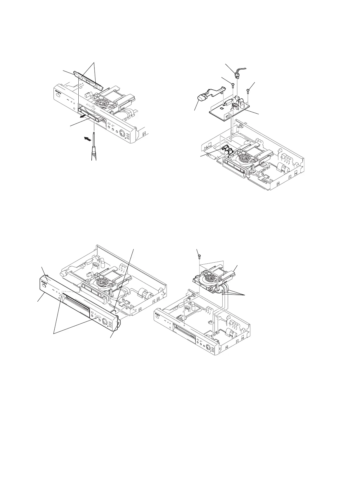
2-5. TRAY COVER REMOVAL 2-7. POWER BLOCK REMOVAL
2-6. FRONT PANEL REMOVAL 2-8. MECHANISM DECK REMOVAL
2 Pull the tray in the
direction of arrow B.
3 Two claws
4 Tray cover
1 Insert a tapering driver into the aperture of the
unit bottom, and move the lever of chuck cam
in the direction of arrow A.
B
A
4 Two claws
5 Front panel
2 Claw
3 Claw
1 Connector (CN402)
1 Connector (CN101)
2 Connector (CN201)
3 Two screws
(WHDB3)
5 Joint (POWER)
4 Two screws
(WHDB3)
6 Power block
2 Three screws (B3)
3 Mechanism deck
1 Three flexible flat cables
(FMO-001: CN201/
FMO-002: CN202/
FMM-035: CN402)