6-15
S
H
U
F
F
L
E
Digital
MPEG
DTS
DISC
PBC
ANGLE
REPEAT 1
PGM
A- B
NTSC
TITLE
TRACK
CHAP
INDEX
HOUR
MIN SEC
VIDEO CD
D V D
C D
S
H
U
F
F
L
E
Digital
MPEG
DTS
DISC
PBC
ANGLE
REPEAT 1
PGM
A- B
NTSC
TITLE
TRACK
CHAP
INDEX
HOUR
MIN SEC
VIDEO CD
D V D
C D
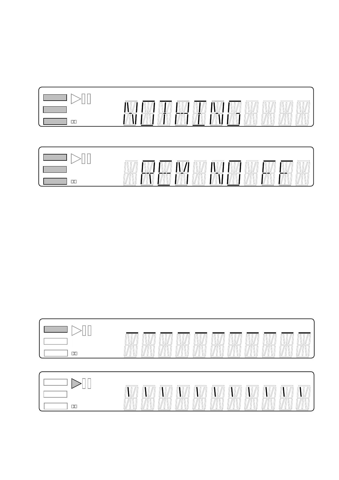
2-3-4. Communication Monitoring Display
The communication state is monitored and displayed while the
key name on the main unit and the remote commander is displayed.
When the communication to the System Controller failed, VIDEO
CD, DVD, and CD segments turn on.
Communication error display (at no key input)
S
H
U
F
F
L
E
Digital
MPEG
DTS
DISC
PBC
ANGLE
REPEAT 1
PGM
A- B
NTSC
TITLE
TRACK
CHAP
INDEX
HOUR
MIN SEC
VIDEO CD
D V D
C D
S
H
U
F
F
L
E
Digital
MPEG
DTS
DISC
PBC
ANGLE
REPEAT 1
PGM
A- B
NTSC
TITLE
TRACK
CHAP
INDEX
HOUR
MIN SEC
VIDEO CD
D V D
C D
Communication error display (at code display without input of
the remote commander)
2-3-5. FLD Anode Test Display and SHUTTLE Click
Operation Test
2-3-5-1. Transition Keys in Self Check Mode
•
[RIGHT] on the main unit and the remote commander
• SHUTTLE on the remote commander during Anode Test dis-
play
(This model does not provide JOG/SHUTTLE, and therefore
use another DVD remote commander having the JOG/
SHUTTLE)
2-3-5-2. Operation and Display
The Self Check mode transits to this mode when [RIGHT] key is
entered. Only the first segment of each grid of FLD turns on, and
each time the SHUTTLE is entered, the segment of each grid is
switched in order. When SHUTTLE input is clockwise, the seg-
ment switches in 1 → 2 → 3 direction, or counterclockwise it
switches in 3 → 2 → 1 direction. This tests whether each segment
turns on individually.
Display at the start of Anode Test
↓ (Input in CW direction)