67
STR-DA1000ES/DB790
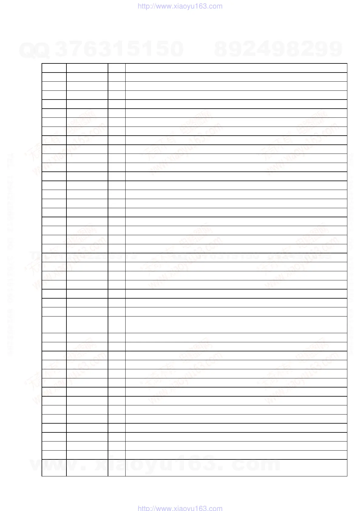
• DIGITAL BOARD IC1601 MB90478PF-G-148-BND (SYSTEM CONTROLLER)
Pin No.
Pin Name
I/O Description
1 DATA0
I
Audio serial data input from the digital audio interface receiver
2 GP9
I
Read ready signal input from the audio digital signal processor
3 BST
O
Boot strap signal output to the audio digital signal processor
4 HCS
O
Chip select signal output to the audio digital signal processor
5HACN
I
Acknowledge signal input from the audio digital signal processor
6 XRST
O
System reset signal output to the audio digital signal processor “L”: reset
7PM
O
PLL initialize signal output to the audio digital signal processor
8 RST
O
System reset signal output to the D/A converter “L”: reset
9 CLK
O
Serial data transfer clock signal output to the D/A converter
10 DATA OUT
I
Serial data input from the D/A converter
11
VSS
—
Ground terminal
12 LAT
O
Serial data latch pulse signal output to the D/A converter
13 DATA IN
O
Serial data output to the D/A converter
14 DATA
O
Serial data output to the tuner unit, function switch and electrical volume
15 CLK
O
Serial data transfer clock signal output to the tuner unit, function switch and electrical volume
16 LATCH
O
Serial data latch pulse signal output to the function switch and electrical volume
17 PCM1748 LAT
O
Serial data latch pulse signal output to the D/A converter
18 HDOUT
I
Serial data input from the audio digital signal processor
19 HDIN
O
Serial data output to the audio digital signal processor
20 HCLK
O
Serial data transfer clock signal output to the audio digital signal processor
21 GP12
O
Write signal output to the audio digital signal processor
22 AD RST
O
System reset signal output to the A/D converter “L”: reset
23
VCC5
—
Power supply terminal (+3.3V)
24 D-POWER
O
Digital section power on/off control signal output terminal “H”: power on
25 ANA/DIG
O
Analog/digital selection signal output terminal “L”: analog, “H”: digital
26 V-POWER
O
Video section power on/off control signal output terminal “H”: power on
27
FLASH2
O
Flash programming signal output terminal
28
SP SWITCH/
FLASH1
I/O
Speaker switch input terminal “L”: speaker on
Flash programming signal output terminal
29
C/SB RY
O
Relay drive signal output terminal (for center/surround back speaker) “H”: relay on
30
SPB RY
O
Relay drive signal output terminal (for front B speaker) “H”: relay on
31 PCM SW
O
Not used
32 LRCK SW
O
Signal selection signal output terminal “L”: boot strap signal, “H”: L/R sampling clock signal
33 SCL
O
Serial data transfer clock signal output to the EEPROM
34 SDA
I/O
Two-way data bus with the EEPROM
35 AVCC
—
Power supply terminal (+3.3V) (for analog)
36 AVRH
I
Reference voltage (+3.3V) input terminal
37 AVSS
—
Ground terminal (for analog)
38, 39
A/D0, A/D1
I
Front panel key input terminal (A/D input)
40 RDS SIGNAL
I
RDS signal input from the tuner unit (STR-DB790: AEP and UK models only)
41 VERSION
I
Destination setting terminal
42 VSS
—
Ground terminal
43 DETECT
I
Voltage limit detection signal input terminal
44
MENU
ENCODER A
I
Jog dial pulse input from the rotary encoder (A phase input) (for MENU)
w
w
w
.
x
i
a
o
y
u
1
6
3
.
c
o
m
Q
Q
3
7
6
3
1
5
1
5
0
9
9
2
8
9
4
2
9
8
T
E
L
1
3
9
4
2
2
9
6
5
1
3
9
9
2
8
9
4
2
9
8
0
5
1
5
1
3
6
7
3
Q
Q
TEL 13942296513 QQ 376315150 892498299
TEL 13942296513 QQ 376315150 892498299
http://www.xiaoyu163.com
http://www.xiaoyu163.com