www.spacelabshealthcare.com
4-7
XPREZZON AND QUBE
O
PERATIONS MANUAL
D ISPLAY OPTIONS
Connectors and Mounting
The setup and maintenance information is contained in the XPREZZON (P/N 070-
2155-xx) or qube (P/N 070-2451-xx) service manuals on the Service CD (P/N 084-
0700-xx)
Connectors
The connectors differ between the 94267-19 and the -L17, -L19, and -L15.
Refer to the Figures for the different connections for each display:
• Display connections for 94267-19 on page 4-7
• Display connections for 94267-L15, 94267-L17, and 94267-L19 on page 4-8.
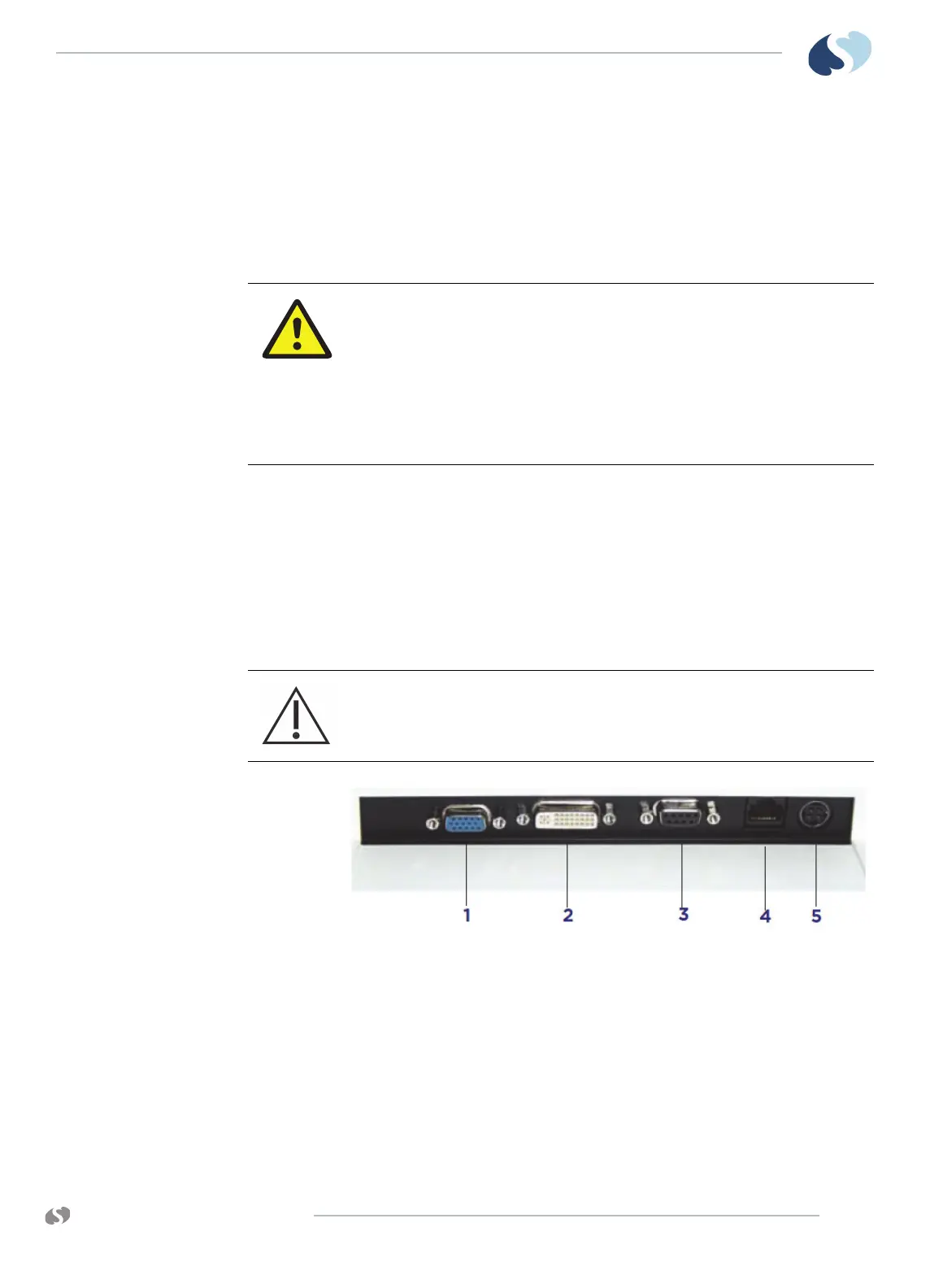
Figure 4-3 Display connections for 94267-19
1 VGA analog in (not used)
2 DVI video in, analog or digital connector
3 Touchscreen serial port
4 Audio in and alarm lights (RJ50)
5 DC Power in (12 VDC)
Equipment connected to the analog or digital interfaces must comply with
the respective IEC standards (e.g. IEC 60950 for data processing equipment
and IEC 60601-1 for medical equipment). Furthermore, all configurations
shall comply with the current version of the standard for SYSTEMS IEC 60601-
1-1. Everybody who connects additional equipment to the signal input part
or signal output part configure a medical system, and is therefore
responsible that the system complies with current version of the
requirements of the system standard IEC 60601-1-1. If in doubt, consult the
technical service department or your local representative.
Before connecting the cables to the flat panel display and Spacelabs
Healthcare monitor, be sure that all components are powered OFF.
 Loading...