26
Line Out
Expansion
Aux. Input
iPod Base
24V DC
12V DC 1 AMP
Adaptor Port
Aux. Input USB
Line Out
Expansion
Aux. Input
iPod Base
24V DC
Line Out
Expansion
Aux. Input
iPod Base
24V DC
Line Out
Expansion
Aux. Input
iPod Base
24V DC
Line Out
Expansion
Aux. Input
iPod Base
24V DC
Line Out
Expansion
Aux. Input
iPod Base
24V DC
12V DC 1 AMP
Adaptor Port
Aux. Input USB
12V DC 1 AMP Adaptor Port Aux. Input USB
12V DC 1 AMP
Adaptor Port
Aux. Input USB
12V DC 1 AMP
Adaptor Port
Aux. Input USB
12V DC 1 AMP Adaptor Port Aux. Input USB
MODE ADAPTER #1
MODE ADAPTER #2
MODE ADAPTER #3
MODE ADAPTER #4
MODE ADAPTER #5
MODE ADAPTER #6
MODE BASE #1
MODE BASE #2
MODE BASE #3
MODE BASE #4
MODE BASE #5
MODE BASE #6
Adapter
Port
iPod Base
Port
Line Out
Adaptor
Interconnect
CAT5
CAT5
CAT5
CAT5
CAT5
CAT5
CAT5 To MZC Expansion Port
One Connection for all Adapters
Stereo Mini
to RCA
To MZC
Source In
Stereo Mini
to RCA
To MZC
Source In
Stereo Mini
to RCA
To MZC
Source In
Stereo Mini
to RCA
To MZC
Source In
Stereo Mini
to RCA
To MZC
Source In
Stereo Mini
to RCA
To MZC
Source In
SpeakerCraft
PS-3.0 24VDC
Power Supply
One Powers all Adapters
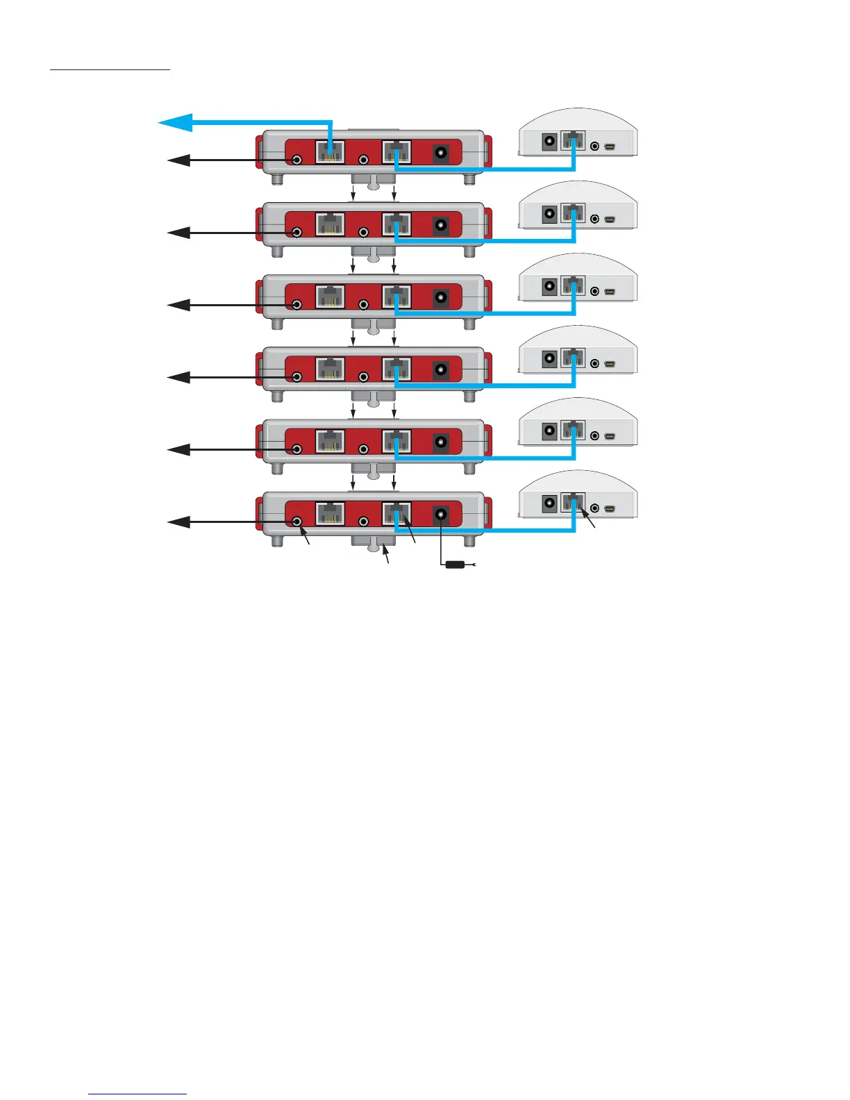
MODE ADAPTER (Stacked)
1. Stack the Adapters and confi rm connection of the 12-Pin Interconnects as described in section: Installation.
2. Using a CAT5 patch cable with a pass-through confi guration, connect the Expansion Port on one of the MODE Adapters
to the Expansion Port on a MZC-64/66/88. (The 12-Pin Interconnects create a bus for power, control and metadata to
the additional units.)
3. Using the included stereo mini to RCA interconnect cables, connect the 3.5mm Line Out Jack on each Adapter to the
appropriate Source Input on the MZC-64/66/88.
4. Using a CAT5 patch cable with a pass-through confi guration, connect the iPod Base Port on each MODE Adapter to
the Adapter Port on its specifi cally matched MODE Base. Repeat until all Adapters and Bases are connected. If CAT5
cable was pulled during pre-wire and terminated with a wall plate in the remote zone, connect the cable to the iPod
Base Port on the MODE Adapter. Connect the RJ45 jack on the wall plate to the Adapter Port on the MODE Base using
a CAT5 patch cable with a pass-through confi guration.
5. Aux Input (optional) - Using a stereo mini to RCA interconnect cable, connect the L&R line level audio output of a
source to be added as an additional input such as an XM or Sirius Tuner, Cable or Satellite receiver, etc. to the Aux
Input on the appropriate Adapter as confi gured in Source Setup in EZ-Tools. This will allow adding up to six additional
sources to the MZC. These inputs must be confi gured in EZ-Tools and are only selectable from MODE Keypads.
6. When all connections have been made and confi rmed and the system is ready for operation, connect a
Speaker-
Craft PS-3.0 Power Supply to the 24V DC Jack on one MODE Adapter. This will provide power for up to six MODE Adapt-
ers. Plug the PS-3.0 into an unswitched 120VAC outlet.
Figure 19
Multiple MODE Adapter/Base Connections
CONNECTIONS
 Loading...