16
WIRING (Pre-wire)
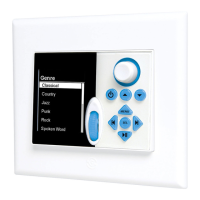
The MODE 3.1 Keypad requires connection to a SpeakerCraft MZC-64, 66 or 88 to operate. The MODE Free Keypad requires
either a MODE Free Wall Dock (hardwire) or MODE Free Coordinator (RF), to communicate with a SpeakerCraft MZC-64, 66
or 88. All system wiring considerations for a MZC system should be followed as described in the MZC-64, 66 and 88 Installa-
tion Instructions. The information below will only detail those parts of a MZC System that pertain to the wiring requirements
for connecting a MODE 3.1 or MODE Free Keypad, MODE Free Wall Dock, MODE Free Coordinator, MODE Adapter and
MODE Base.
NOTE: The following wires should be installed during system pre-wire. Other connections will be made at the time of installa-
tion and are described in section: Connections.
MODE 3.1 KEYPAD
Control/Metadata
CAT5 - Pull home-runs of CAT5 from each MODE 3.1 location to the system head-end. MAXIMUM LENGTH: 500’
NOTE: All eight conductors of the CAT5 must be connected for proper signal strength on 500’ of cable.
Speaker Relay Mute (MODE 3.1 only)
STANDARD WIRE - Pull two-conductor 24AWG or heavier, stranded, non-shielded wire from any MODE 3.1 location to
where a SpeakerCraft EPR-1.0 Speaker Relay Muting Module will be installed. MAXIMUM LENGTH: 1000’
MODE ADAPTER
Expansion Port
CAT5 - Pull CAT5 from the MZC to where the MODE Adapter(s) will be installed. For installations where the Adapter
will be at the system head-end, a CAT5 patch cable can be used at time of installation and hook-up. For installations
where the Adapter will be in a remote location, pull CAT5 during pre-wire and terminate with a proper wall plate.
MAXIMUM LENGTH: 50’.
NOTE: When stacking Adapters, only one run of CAT5 is required between the Adapters and the MZC. See section: Con-
nections/MODE Adapter (Stacked) for additional information.
iPod Base
CAT5 - Pull CAT5 from the MODE Adapter(s) to the MODE Base(s). For installations where the Base(s) will be at the
system head-end, a CAT5 patch cable can be used at time of installation and hook-up. For installations where the
Base will be in a remote location, pull CAT5 during pre-wire and terminate with a proper wall plate. The Base will then
connect to the wall-plate during installation. MAXIMUM LENGTH: 250’ when powered from Adapter; 500’ when Base is
powered locally with a SpeakerCraft PS-2.0 power supply (not included).
MODE BASE
12V DC 1AMP
STANDARD WIRE - For installations where the Base will be connected to the MODE Adapter via a wall-plate, pull 16AWG
two-conductor stranded non-shielded wire from the PS-2.0 power supply location, typically the head-end, to the Base
location, as shown in Figure 6. MAXIMUM LENGTH: 500’ on 16AWG wire.
Adapter Port
CAT5 - Pull CAT5 from the MODE Adapter(s) to the MODE Base(s). For installations where the Base(s) will be at the sys-
tem head-end, a CAT5 patch cable can be used at time of installation and hook-up. For installations where the Base
will be in a remote location, pull CAT5 during pre-wire and terminate with a proper wall plate. The Base will then con-
nect to the wall-plate during installation. MAXIMUM LENGTH: 250’ (When powered from Adapter); 500’ when Base is
powered with a SpeakerCraft PS-2.0 power supply (not included).

 Loading...