11
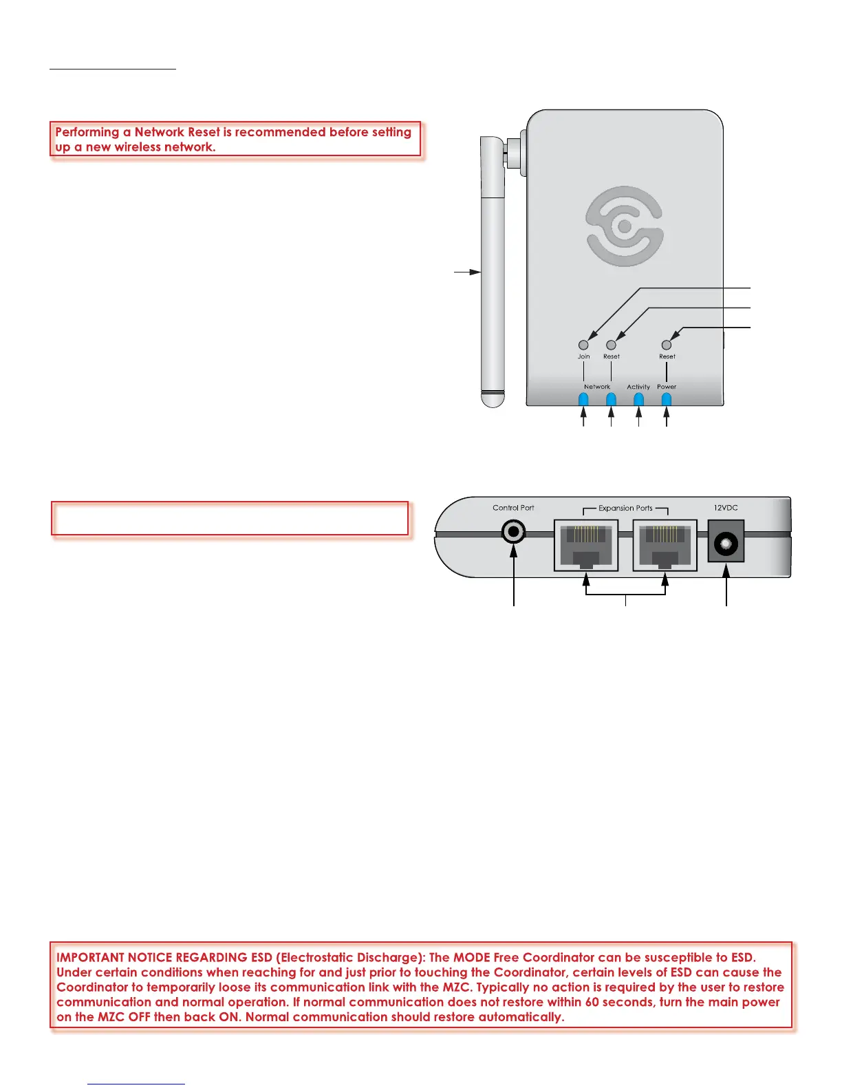
45
46
47
48
49505152
Figure 7
MODE Free Coordinator Communication Features
53 54 55
Figure 8
MODE Free Coordinator Connection Features
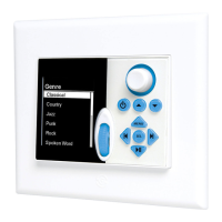
MODE FEATURES
MODE FREE COORDINATOR FEATURES
Performing a Network Reset is recommended before setting
up a new wireless network.
45. ANTENNA - The antenna transmits/receives RF signals
for control and metadata to/from the MODE Free. The
antenna can be rotated and angled for optimum recep-
tion.
46. JOIN NETWORK SWITCH - One, recessed switch, is pressed
to initiate wireless network communication between a
Coordinator and MODE Free. This switch is used in con-
junction with the ‘Join Network’ function in the MODE
Free Network Settings Menu.
47. RESET NETWORK SWITCH - One, recessed switch, is pressed
for 2 seconds to delete wireless network settings. Typically
used when the Coordinator and MODE Free are expe-
riencing communication problems, to reset the wireless
network. Pressing this switch will break RF communication
with all MODE Frees in the system. To remove a single
MODE Free, use the ‘Leave Network’ function in the
MODE Free Network Settings Menu.
48. RESET SWITCH - One, recessed switch, is pressed to per-
form a power or hardware reset.
49. POWER LED - One, blue LED fl ashes when the Coordina-
tor is receiving DC power from the MZC via one of the
Expansion Ports (typical) or when connected to a Speak-
erCraft PS-1.0 Power Supply.
50. ACTIVITY LED - One, blue LED fl ashes to indicate wireless
network activity.
51. RESET NETWORK LED - One, blue LED fl ashes during network reset, until current settings have been deleted.
52. JOIN NETWORK LED - One, blue LED fl ashes during Network Join process until the MODE Free being joined has been
added to the RF Network.
53. CONTROL PORT - One, 3.5mm three-circuit mini jack connects to a PC running EZ-Tools for upgrading Coordinator Firm-
ware.
54. EXPANSION PORTS - Two, RJ45 jacks, are primarily used to connect the Coordinator to an Expansion Port on a Speaker-
Craft MZC Controller. This connection powers the Coordinator and provides all communication between the MODE Free
and the MZC for system and source control and transmission of source metadata to the MODE Free, when the MODE
Free is in wireless mode. These jacks can also be used for connection of specialized RS485 controlled devices such as
the SpeakerCraft MODE Base for adding iPods and additional sources (see sections: Connections MODE Adapter and
MODE Base) and the SpeakerCraft RSA-1.0 for control of up to 16 additional RS232 devices. (See RSA-1.0 Installation
Instructions for additional information.)
55. 12VDC JACK - One, 2.1mm coaxial jack, connects to a SpeakerCraft PS-1.0 Power Supply when the CAT5 cable be-
tween the Coordinator and MZC is longer than 500’ (152m).
IMPORTANT NOTICE REGARDING ESD (Electrostatic Discharge): The MODE Free Coordinator can be susceptible to ESD.
Under certain conditions when reaching for and just prior to touching the Coordinator, certain levels of ESD can cause the
Coordinator to temporarily loose its communication link with the MZC. Typically no action is required by the user to restore
communication and normal operation. If normal communication does not restore within 60 seconds, turn the main power
on the MZC OFF then back ON. Normal communication should restore automatically.
A power/hardware reset will not remove the wireless net-
work settings.
 Loading...