13
0
1
2
3
4
5
6
7
8
9
A
B
C
D
E
F
57 58 59 60 59 61
6263
MODE FEATURES
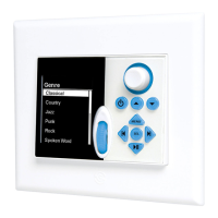
MODE FREE WALL DOCK FEATURES
57. LOCK TABS - Two non-moving tabs insert into matching
slots on the MODE Free to secure the keypad to the Wall
Dock. The Lock Tabs should be inserted into the MODE
Free Lock Tab Slots before pressing the keypad down
over the Locking Mechanism (Item 61).
58. CONTACT TERMINAL - Twelve, spring loaded conduc-
tive pins convert a docked MODE Free to a hard wired
keypad, connected to the MZC via a CAT5 cable con-
nected between the Wall Dock and MZC. When docked,
RF communication between the MODE Free and Coordi-
nator is disabled, the MODE Free assumes the ‘identity’ of
the programming confi guration for the MZC Zone the Wall
Dock is connected to and the keypad is powered from
the Wall Dock while the battery automatically re-charges.
59. WALL DOCK MOUNTING SCREWS - Two screws secure the
Wall Dock to the MODE Free Back Box.
60. DOOR HANDLE - Molded Tab allows opening and closing
the Wall Dock Door. The door can be closed when the
MODE Free is undocked. (Figure 10 shows in door open
position; Figure 12 shows closed position.)
61. LOCK MECHANISM - Four mechanical tabs insert into
matching slots on the MODE Free to secure the keypad to
the Wall Dock. The Lock Tabs (Item 57) should be inserted
into the MODE Free Lock Tab Slots before pressing the
keypad down over the Locking Mechanism. To release
the MODE Free, press the Keypad Release Button (Item 9)
on the front of the keypad.
62. CHARGING LED - One, blue LED illuminates when the re-
chargeable lithium-ion battery in a docked MODE Free
is charging. The LED turns off when the battery is fully
charged.
63. ADDRESS SWITCH - A unique HEX address must be set for
each MODE Free (Wall Dock), MODE 3.1 Keypad or EZ-
Pad when connected on a common bus within a single
zone. Unique addresses are not required zone-to-zone
(One Wall Dock or keypad per zone). The switch provides
up to 16 HEX addresses (0 to F).
64. DOOR TRACK - Slotted track protects the retracting door
when rolled back into the wall cavity while in the open
position.
65. RJ45 CONNECTION PORT - One, RJ45 jack connects the
Wall Dock/MODE Free to a Zone Keypad Port on a MZC
Controller via CAT5 or better cable. (CAT5 should be con-
figured in a pass-through, pin to pin, configuration.)
Figure 10
MODE Free Wall Dock (Door Open)
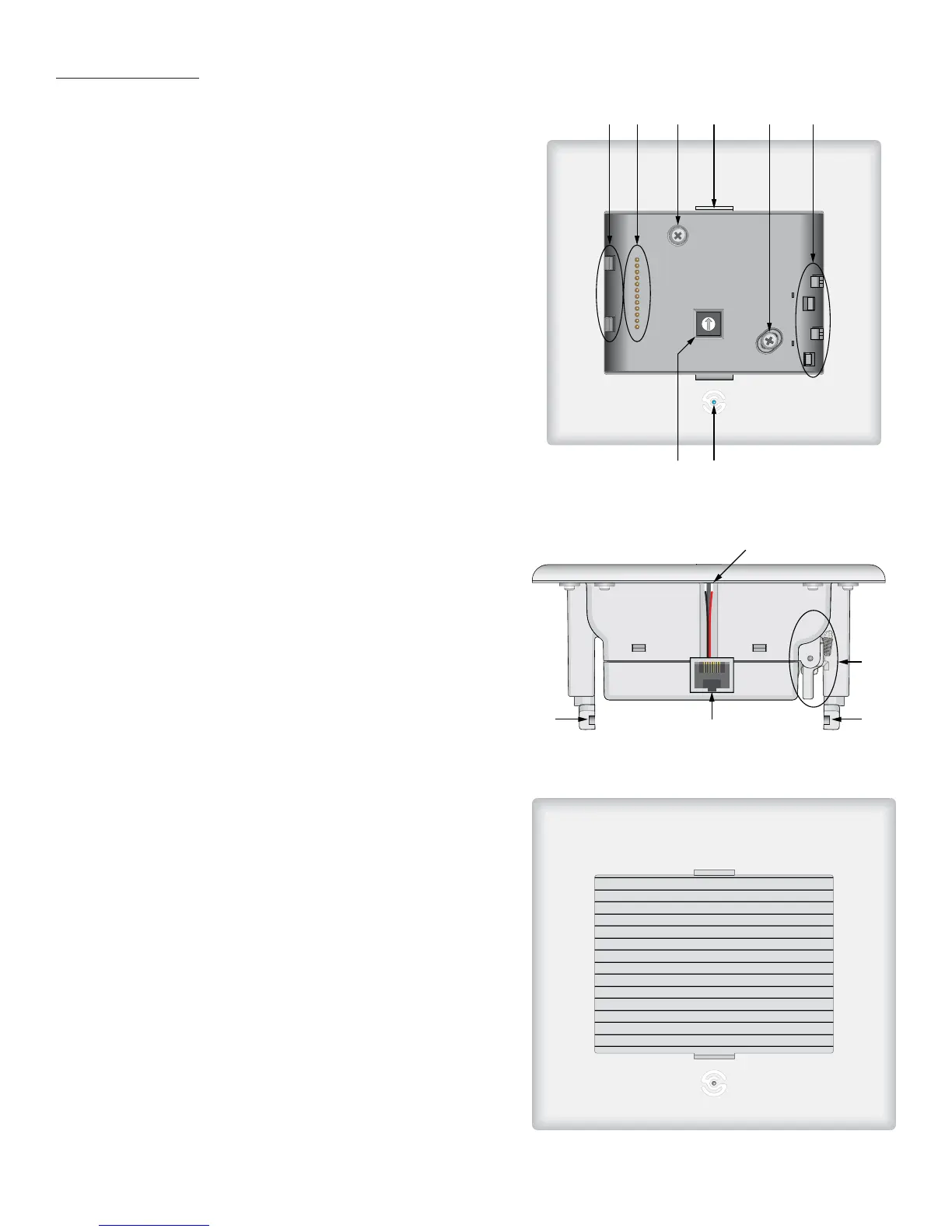
Figure 12
MODE Free Wall Dock (Door Closed)
62
61
6464
65
Figure 11
MODE Free Wall Dock (Side View)
 Loading...