8
Line Out
Expansion
Aux. Input
iPod Base
24V DC
MODE Adaptor
Riverside, CA www.speakercraft.com
MADE IN CHINA
21 22 21
2323
21 25 24 21
26 27 28 29
30
31 32 33 6
2323
26 22 26
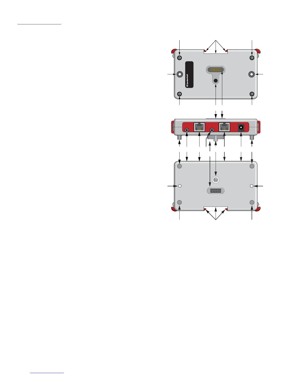
MODE FEATURES
MODE ADAPTER FEATURES
21. ADAPTER POST SOCKETS - Four recessed sockets used to
align Adapter Posts, to secure multiple Adapters and pre-
vent damage to Adapter Bus Pins.
22. DIN RAIL SLOT AND CLIPS - Allows the MODE Adapter to be
wall mounted using standard DIN Rail (not included). Red
clips slide over the rail section to hold the Adapter in place.
‘Stacked’ Adapters can also be mounted on DIN Rail.
23. WALL MOUNT SCREW HOLES - These holes allow the MODE
Adapter to be mounted fl at against a wall or cabinet side.
24. 12 PIN INTERCONNECT - Connect to the 12 pin socket on
the bottom of a stacked Adapter. This connection creates
a power, metadata and control bus that allows stacking
multiple MODE Adapters.
25. LOCKING PIN SLOT - Round opening on the top of the
Adapter used to receive and lock Locking Pins when stack-
ing multiple Adapters.
26. ADAPTER POSTS - Four round posts on the bottom of the
Adapter protect the 12 Pin Interconnect when single
Adapters are used and fi t into the Adapter Post Sockets
when stacking multiple Adapters to hold Adapters in place
and prevent damage to the interconnects.
27. LINE OUT - 3.5mm stereo mini jack outputs stereo line level
audio. Connects to MZC Source Input via the included 10
foot stereo mini-plug to RCA interconnect cable. When
stacking multiple Adapters, each Adapter must be con-
nected to a dedicated Source Input on the MZC.
28. EXPANSION PORT - RJ45 Jack connects to the Expansion
Port on the MZC Rear Panel to Rx/Tx control and metadata
between the MZC and MODE Adapter.
29. AUX INPUT - 3.5mm stereo mini jack provides a stereo line
Figure 4
MODE Adapter Features
level input for an additional source. This could be anything from a cable/satellite receiver, to an XM or Sirius Tuner or
a DVD player allowing up to 12 Sources on an MZC-64, 66 or 14 Sources on an MZC-88 (including on-board tuners).
Switching to and controlling the sources connected to this input must be confi gured during setup in EZ-Tools. Only
MODE Keypads have access and control of the devices connected to the Aux Inputs. EZ-Pads do not have access to
or control of these devices.
30. 12 PIN INTERCONNECT SOCKET - 12 pin socket connects to the 12 Pin Interconnect on the top of a stacked Adapter. This
connection creates a power, metadata and control bus that allows stacking multiple MODE Adapters.
31. LOCKING PIN - Metal post on the Adapter bottom fi ts into the Locking Pin Slot when stacking Adapters. Use a medium
size fl at head screwdriver to turn the post and lock the stacked Adapters together.
32. iPOD BASE RJ45 TERMINAL - RJ45 jack connects to the Adapter Port on a MODE Base via CAT5. This connec-
tion provides power and control to the iPod/Base and receives digital audio data and metadata from a
connected iPod.
33. 24V DC - 2.1mm coaxial jack connects to a SpeakerCraft PS-3.0 24V Power Supply (Required/Not includ-
ed). When stacking Adapters, one PS-3.0 will power up to 6 MODE Adapters.
 Loading...