28
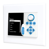
MODE 3.1 Connections
1. Strip approximately 1” to 1.5” from the outer jacket of the cable being connected to the MODE 3.1. DO NOT strip the
individual conductors.
2. Using a proper punch-down tool, connect each of the wires to the matching color terminals on the MODE 3.1 punch-
down block. When making connections to the MODE 3.1 punch-down block ALWAYS pull the wire toward the middle of
the 3.1. Pulling the wires toward the outside will create diffi culty when installing the keypad into the Mounting Bracket
and will probably cause wires to become disconnected.
3. Prior to installing the keypad, attach the included Wire Retainer to the back of the MODE 3.1 as shown in Figure 22.
Remove the adhesive backing from the wire retainer and attach with the wire tie oriented vertically as shown, with the
retainer lock at the bottom. Pull the retainer over the wire and down through the lock as shown. This will help prevent
the wires from becoming disconnected during installation.
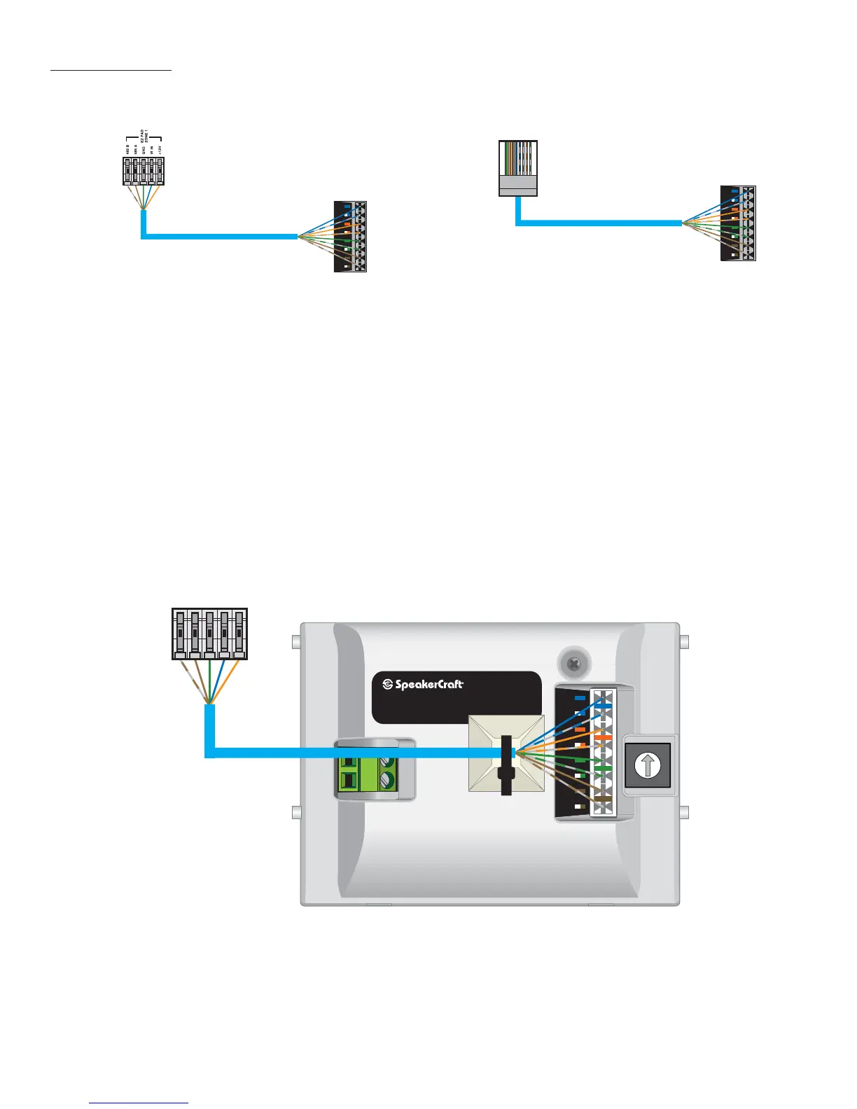
3. Terminate and connect the head-end connection as appropriate. If connecting directly to an MZC-66 or KCM-1.0,
Refer to Figure 20. If terminating in RJ45 Connectors and connecting to a MZC-64 or using RJA-1.1s Refer to Figure 21.
Confi rm all connections prior to powering up the system.
IR
IR
+12
+12
GND
GND
485 A
485B
0
1
2
3
4
5
6
7
8
9
A
B
C
D
E
F
+ RELAY
- RELAY
ADDRESS
MODE 3.1
Riverside, CA www.speakercraft.com
MADE IN CHINA
Figure 22
MODE Wire Retainer
1
2345678
IR
IR
+12
+12
GND
GND
485 A
485B
To MZC-64 Zone Terminal or
RJA-1.1 CAT5 to MZC Adaptor
MODE 3.1
Punch-Down Block
NOTE: When making connections
to the MODE 3.1 punch-down block
ALWAYS pull the wire toward the
middle of the 3.1. Pulling the wires
toward the outside will create difficulty
when installing the keypad into the Mounting Bracket
and will probably cause wires to become disconnected.
CAT5
IR
IR
+12
+12
GND
GND
485 A
485B
MZC-66 or
KCM-1.0 Zone Terminal
MODE 3.1
Punch-Down Block
NOTE: When making connections
to the MODE 3.1 punch-down block
ALWAYS pull the wire toward the
middle of the 3.1. Pulling the wires
toward the outside will create difficulty
when installing the keypad into the Mounting Bracket
and will probably cause wires to become disconnected.
CAT5
NOTE: When connecting
GND, IR IN and +12V, connect
both of the same color
solid and striped wires.
Figure 20
MODE to MZC Connections
Figure 21
MODE to RJA-1.1 Connections
CONNECTIONS
 Loading...