SC5 Signal Conversion Instrument Overview
12
The eight analog outputs (AO) on the front panel consist of a 20-bit 1 MS/s DAC, followed by a 5
th
order low-pass
filter with a corner frequency of 40 kHz (-3 dB). Bipolar (-10 V to +10 V output range) or unipolar (0 V to +10 V
output range) can be set individually for each channel by adjusting a jumper placed close to the DAC. The jumper
setting is detected by software. The reference voltage for all DACs is provided by a single precision, temperature
stabilized voltage reference. When the SC5 is switched off, all outputs are clamped to AGND. The output stage is
disconnected from the outputs with software-controlled relays during calibration and start-up. The shield of the
output BNC connectors is connected to AGND.
The fast analog output uses the same DAC as the other analog outputs, with the difference being a separate voltage
reference, and an output stage with a 1
st
order low-pass filter with a corner frequency of 1 MHz (-3 dB).
The logic section consists of a complex programmable logic device (CPLD) which takes care of preparing and
transferring digital data between the ADCs and DACs in the SC5 and the FPGA in the Nanonis RC5. It also controls
the input selector switches and the output relays, monitors the status of the bipolar/unipolar jumpers of the outputs,
and the temperature inside the instrument. A clock-cleaning circuit provides a clean, low-jitter reference clock for
the digital section and the AD/DA converters.
The SC5 linear power supply generates three preregulated voltages: ±5 V for the digital circuits (and for the power
LED (3) on the front panel), ±15 V for the analog circuits, and ±15 V for the auxiliary power supply. Each supply
branch uses separate secondary windings of the power transformer. The first two power supplies are connected to
protection earth (PE = chassis of the instrument) by two 10 kΩ resistors in parallel. The GND of the auxiliary power
supply is connected to AGND over a 100 Ω resistor. DGND, AGND and AUX GND are connected to each other
with 100 Ω resistors. The line voltage is selected automatically.
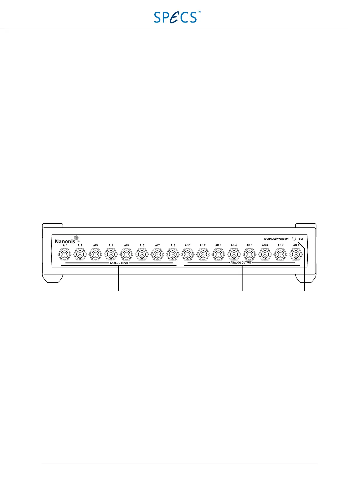
Front panel
Figure 2: SC5 front panel.
1. Analog inputs: The eight BNC plugs AI1 to AI8 are the analog inputs of the SC5. All inputs can accept
voltages up to ±10 V and are differential. The analog bandwidth is 100 kHz (-3 dB). Please refer to the Analog
Inputs section for more details about the input stage.
2. Analog Outputs: The eight BNC plugs AO1 to AO8 are the analog outputs of the SC5. All outputs can deliver
voltages up to ±10 V and currents up to ±20 mA. The shields of the output BNCs are connected to AGND. The
analog bandwidth is 40 kHz (-3 dB). Please refer to the Analog Outputs section for more details about the output
stage.
3. Power LED (blue): Indicates that the instrument is powered up.