SC5 Signal Conversion Auxiliary Power Supply
38
connected to the power supply is drawing too much current (LEDs flashing), or the power supply is faulty and does
not supply enough voltage (LEDs off).
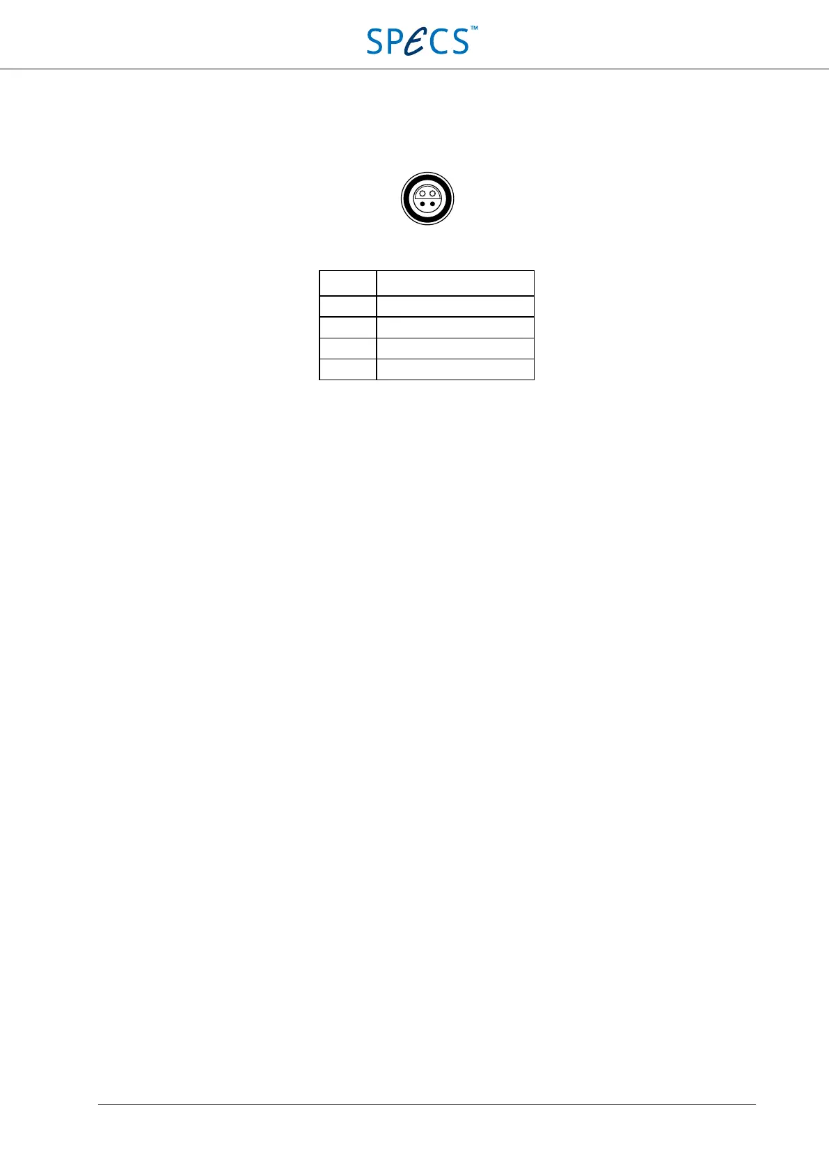
The connector pin configuration is shown in the picture and table below.
Figure 21: Auxiliary power supply receptacle pin layout.
PIN Signal
1 +15 V
2 -15 V
3 AUX power supply GND
4 AUX power supply GND
Table 1: Pin assignment of the auxiliary power supply receptacle.
Note that the casing of the receptacle is connected to PE (in contrast to the Nanonis SC4 and OC4, where the casing
is connected to AUX power supply GND).
Specifications (auxiliary power supply)
Connector LEMO EPL.0S.304.HLN
Voltage ±15 V
Maximum asymmetry < 750 mV (5%)
Maximum current ±300 mA (current limiter)
Minimum load 0 mA
Noise (0.1 Hz – 25 kHz) < 2 mV RMS
Mains transient rejection < 500 ppm @ 10% line voltage change
Load transient rejection < 600 ppm @ 100% load change
Temperature coefficient < 500 ppm/K typical
Hold-up time 3.5 s (idle), 60 ms (50% load), 5 ms (100% load)