SC5 Signal Conversion Auxiliary Power Supply
36
Auxiliary Power Supply
The SC5 is equipped with an auxiliary ±15 V power supply, which can be used to power external instruments like
preamplifiers. It can supply up to ±300 mA, and is fed from a dedicated winding of the power transformer. The
auxiliary power supply connector (9) is located at the back of the instrument, and is a LEMO receptacle model
EPL.0S.304.HLN. The corresponding plug can be obtained from LEMO (model FFA.0S.304.CLAC42, with
“CLAC42” defining the cable diameter range, and therefore depending on the used cable).
The auxiliary power supply provides a pre-regulated supply voltage. Since most instruments powered by the
auxiliary power supply will be placed at relatively large distances from the SC5, it is recommended to use local
voltage regulators if these instruments require very low-noise supply voltages.
The auxiliary power supply is protected against overcurrent by a current detection circuit, which disables the output
when the connected instrument draws more than 300 mA per supply rail. In that case, the status LED (8) of the
overloaded rail will start to flash with a frequency of about 5-10 Hz. The complete power supply of the SC5 is
additionally protected by a thermal fuse in the main transformer, which irreversibly disconnects its primary winding
if the temperature of the core exceeds 115°C.
Connection
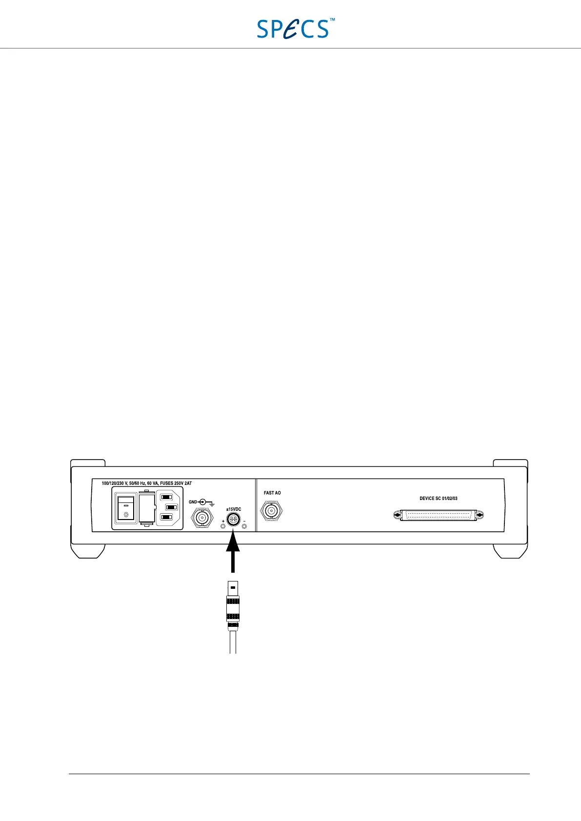
The plug of the instrument to be powered can be simply inserted into the auxiliary power supply socket, as shown
below. It is possible to insert the connector both with the SC5 switched on or off. Should the status LEDs (8) start
flashing when the connector is plugged in, disconnect the connector, and make sure that there are no short circuits in
the power supply path to the external instrument. If there are no short circuits, the instrument is drawing too much
current, and a different power supply should be used. For more details, refer to the Troubleshooting section.
Figure 17: Connection of an external device to the auxiliary power supply on the back of the SC5.