SC5 Signal Conversion Performance Measurements
59
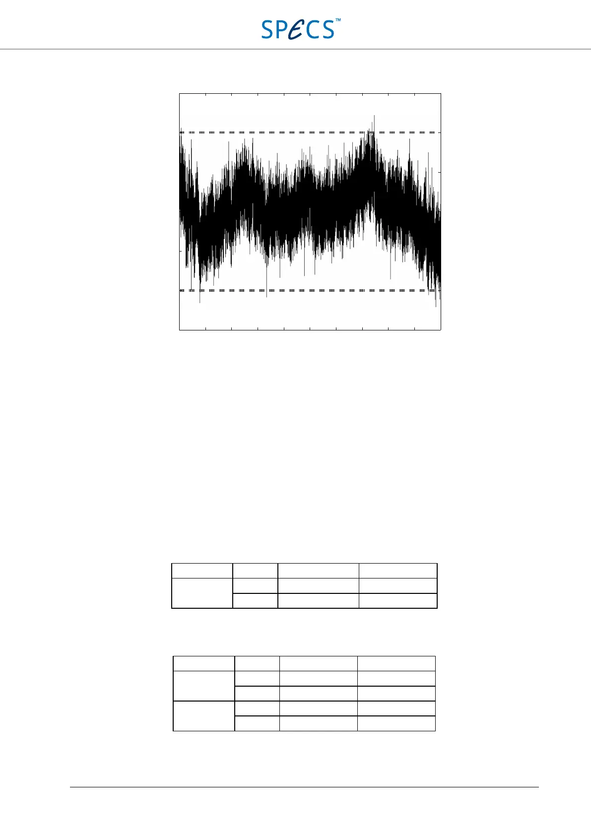
Figure 39: Integral nonlinearity of the analog outputs. The dashed lines indicate the ±1 LSB range. The INL is below ±1
LSB at 20 bit, meaning that the outputs achieve 1-ppm precision.
Offset and gain error
The offset of the SC5 outputs set to 0 V is measured with the SC5 connected directly to a National Instruments 4071
PXI digital multimeter operated in DMM mode (7.5 digits). The maximum absolute offset compared to the DMM,
and the maximum relative offset between channels for uncalibrated and calibrated outputs is shown in the table
below. The following settings have been used for the measurement:
DMM
Measured output: AO1 Mode of operation: DMM, DC volts
Output amplitude: 0 V, ±10 V Range: 100 mV and 10 V
Resolution: 26 bit
Output voltage Calibrated Max. absolute offset Max. relative offset
0 V No ± 550 µV 200 µV
Yes ± 25 µV 40 µV
Table 14: maximum absolute and relative offsets of the SC5 analog outputs.
Gain error is measured at output voltages on -10 V and +10 V.
Output voltage Calibrated Gain error Max. relative offset
-10 V No < 0.85 ‰ of setting 200 µV
Yes < 0.72 ‰ of setting 200 µV
+10 V No < 0.85 ‰ of setting 200 µV
Yes < 0.72 ‰ of setting 200 µV
Table 15: maximum gain error and relative offsets of the SC5 analog outputs at ±10 V.
−10
−8
−6 −4
−2
0 2 4 6 8 10
Output voltage [V]
INL [20-bit LSB]
1.5
1
0.5
0
-0.5
-1
-1.5