SC5 Signal Conversion Performance Measurements
49
Gain error of the SC5 inputs is determined by applying a voltage of -9.9 and +9.9 V from the analog outputs, after
the outputs were calibrated with a National Instruments 4071 PXI 7.5 digit digital multimeter.
Input voltage Calibrated Gain error Max. relative offset
-9.9 V No < 3‰ of reading < 50 mV
Yes < 0.76‰ of reading < 350 µV
+9.9 V No < 3‰ of reading < 60 mV
Yes < 0.75‰ of reading < 100 µV
Table 5: maximum absolute and relative offsets of the SC5 analog inputs.
Accuracy
The accuracy of the analog inputs can be deduced from the offset and gain error measurements. The result for
uncalibrated and calibrated inputs is summarized below:
Calibrated Accuracy error Abs. Accuracy at 0 V Abs. accuracy at ±10 V
No < ±3‰ of reading ± 7 mV < ±7 mV < ±30 mV
Yes < ±0.76‰ of reading ± 25 µV < ± 25 µV < ±7.6 mV
Table 6: Accuracy of the analog inputs.
Input stability and temperature dependence
12 hour stability
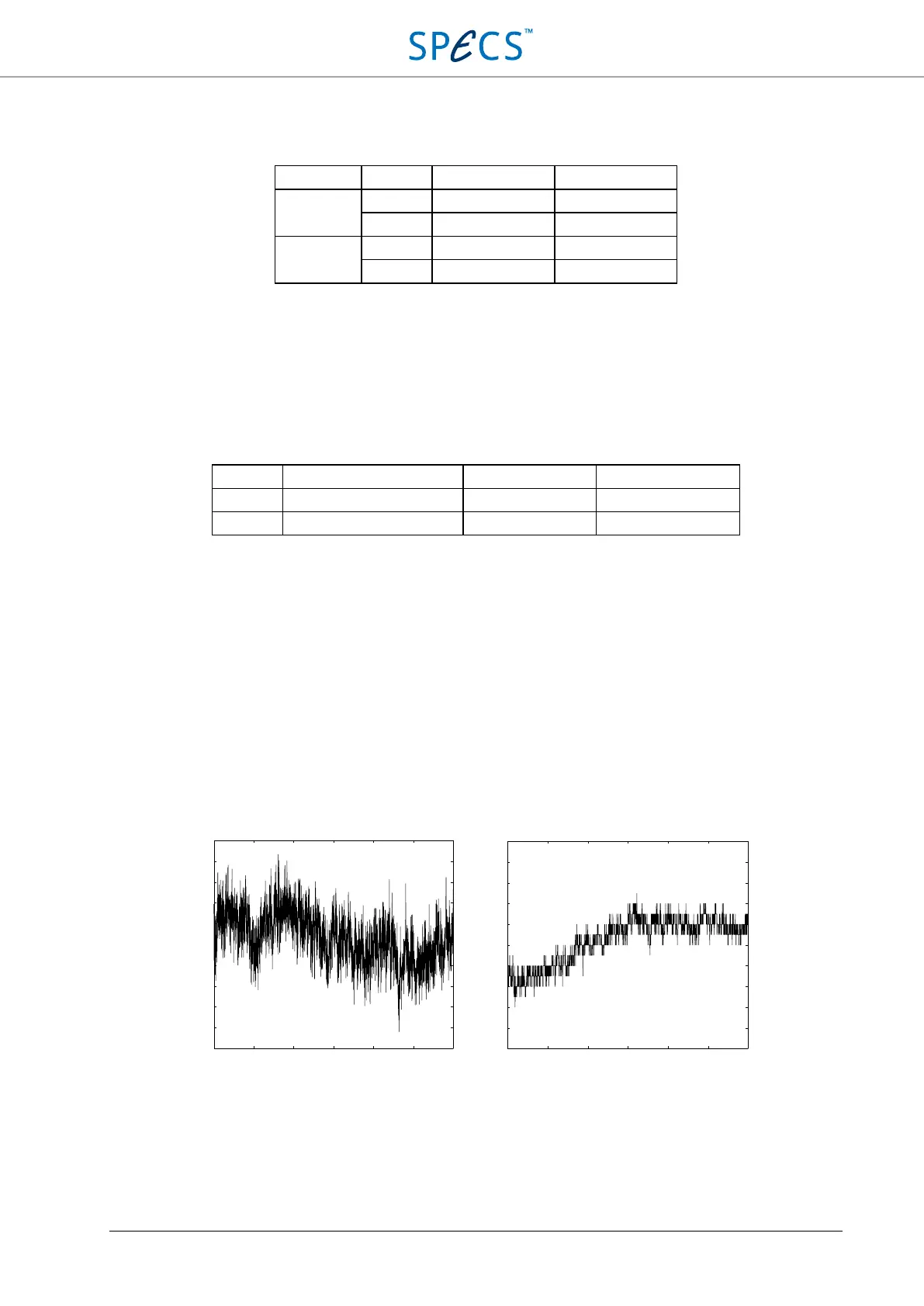
The stability of the input voltage is measured over 12 hours at a 10 seconds interval with AI1 shorted (0 V), and with
AI1 connected to AO1 (+9.9V). In the latter case, the output drift is also present in the measurement. The internal
temperature of the SC5 is also recorded, in order to compare the drift of the output signal with the temperature
coefficient determined below. The results are shown below.
Figure 27: Input drift measurement during 12 hours. The left plot is for 0 V input voltage, the right plot for +9.9 V. The
9.9 V offset has been subtracted in the right plot.
.
0 2 4 6 8 10 12
Time [hrs]
Input voltage [μV]
5
0
40
30
20
10
0
-10
-
20
-30
-40
-50
Input
rang
e: ±1
0 V
Intput: sho
rted
0 2 4 6 8
10 1
2
Time [hrs]
Input voltage [μV - 9.9 V]
100
80
60
40
20
0
-20
-40
-60
-80
-100
Inpu
t rang
e: ±1
0 V
Intp
ut: +9.9 V