SC5 Signal Conversion Analog Outputs
25
Analog Outputs
This chapter explains how to connect the SC5 analog outputs AO1 – AO8 (2) to other equipment, and explains in
more detail the output stages of the instrument. For the fast analog output, please refer to the Fast Analog Output
chapter below.
Analog outputs connection
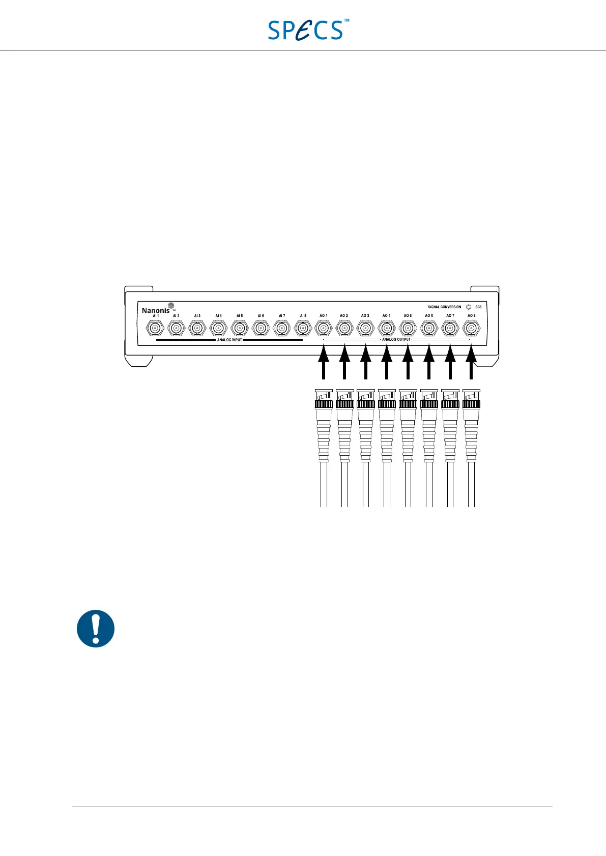
The analog outputs of the SC5 can be connected to the experiment using BNC cables, as shown in the picture below.
Figure 10: Connection of the analog output BNC cables.
There are no external controls for the analog outputs. The output relays (see the Analog outputs schematic section for
details) are controlled by software during the calibration procedure. The outputs are configured for bipolar operation
(output voltage range: -10 V to +10 V) by default. They can be configured for unipolar operation (output voltage
range: 0 V to +10 V) by changing the position of jumpers inside the SC5, as explained in the Bipolar and unipolar
operation section below.
Note: The maximum output current is limited to ± 20 mA. Although the outputs are short-circuit
proof, make sure that this value is not exceeded, otherwise the output drivers will exceed their rated
operating temperature, and their lifetime will be reduced.