SC5 Signal Conversion Analog Outputs
31
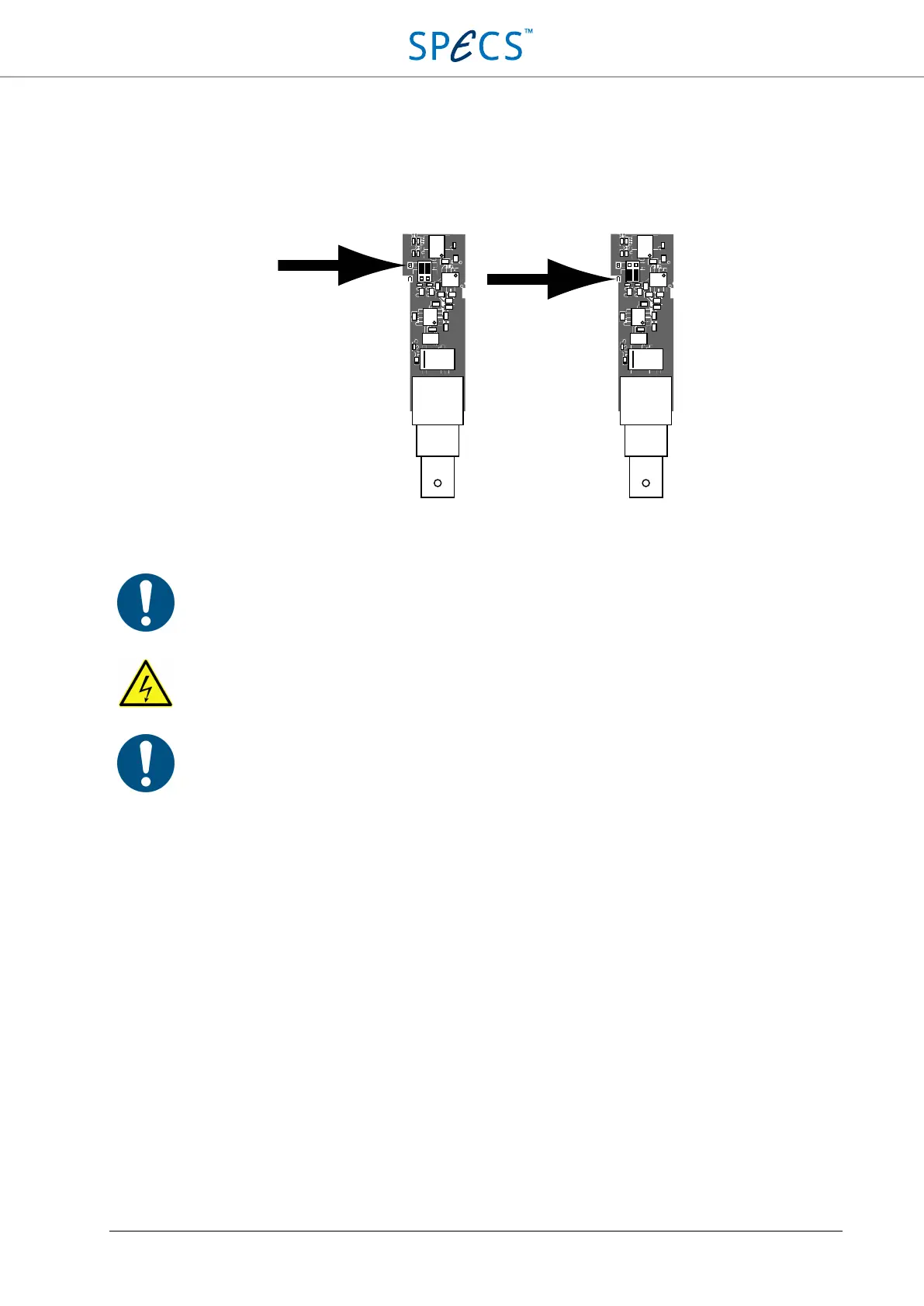
The position of the jumpers is indicated in the figure below. The jumpers can be removed and placed at the desired
position by using small metallic tweezers. The position is marked by a “B” (bipolar) and “U” (unipolar) on the
printed circuit board. Make sure to wear a wrist strap properly connected to ground. Make sure to change the
position of both jumpers of each channel requiring a change of the bipolar/unipolar setting.
Figure 14: Location and setting of the jumpers for the selection between bipolar and unipolar operation. A single channel
including output BNC connector is shown.
Note:
Make sure to change the position of both jumpers of each channel requiring a change of the
bipolar/unipolar setting. Changing the position of only one jumper will lead to a wrong output
calibration. Do not turn the jumpers by 90°, or the instrument will not work properly.
Avoid any physical contact with or modification of the areas of the instrument marked by
the high voltage warning sign, as this might impair the safety of the instrument.
Note: Make sure that the grounding wire is still firmly connected to the top cover and to the rear panel
before closing the instrument. A loose grounding wire will impair safety of the instrument. Also make
sure that no shields, screws, tools, or other objects h
ave been dropped or forgotten inside the
instrument. Any object left inside the instrument might impair safety of the instrument.
hrDAC™
Introduction
Many applications require DA converters with high resolution, accuracy, precision and monotonicity. Although
Sigma-Delta DACs appear to offer very high resolution, they are not suitable for e.g. nanopositioning applications,
where the DAC must have excellent AC and DC characteristics. The 20-bit DACs used in the SC5 are based on a
segmented R-2R architecture, and offer state-of-the-art resolution, accuracy, precision, and monotonicity, along with
excellent AC and DC performance. However, even higher resolution may be desirable.
The resolution can be increased by using pulse-width modulation of the least significant bit (LSB). The modulation
frequency is suppressed by using a low-pass filter, which must have a cut-off frequency 2
m
times lower than the
modulation frequency, with m being the number of bits gained in terms of resolution. Pulse-width modulation does
not, however, increase accuracy, precision and monotonicity, which are bound to the native resolution of the DAC.