SC5 Signal Conversion Analog Outputs
30
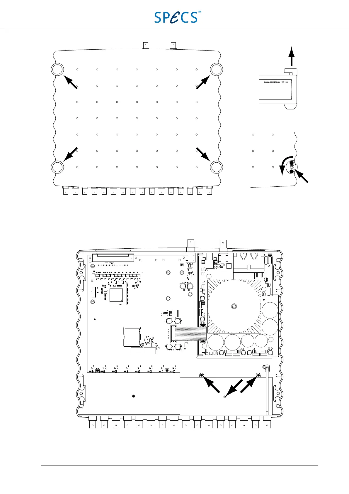
Figure 12: Removing the top cover of the SC5: First remove the four plastic caps covering the screws by lifting them, then
remove the four screws by turning CCW with a 3 mm hex screwdriver.
After removal of the top cover an additional internal shield has to be removed. The shield covers the entire analog
output section, and is located as indicated in the figure below. Remove the three Phillips screws keeping the shield in
position, and then remove the shield.
Figure 13: Internal view of the SC5. The three screws indicated by the arrows need to be removed in order to detach the
metallic shield covering the analog outputs section.