SC5 Signal Conversion Performance Measurements
48
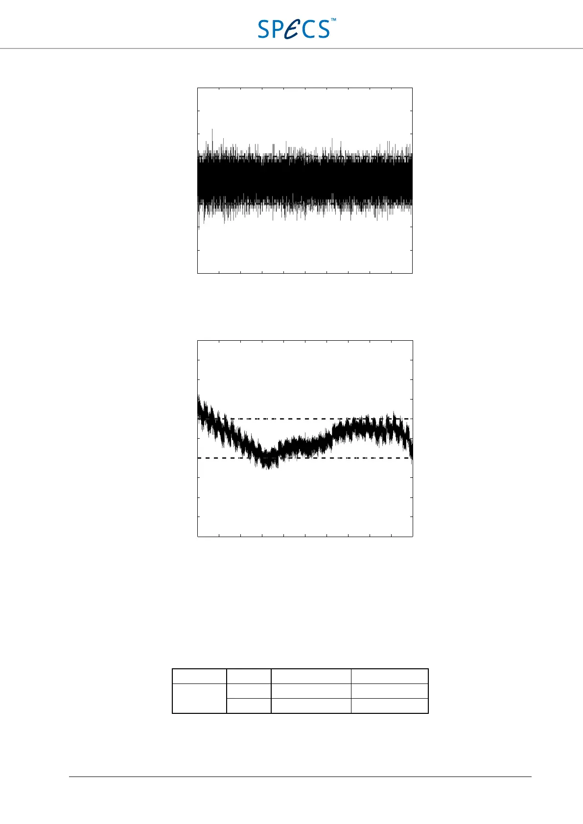
Figure 25: Differential nonlinearity of the analog inputs. The dashed lines indicate the ±1 LSB range.
Figure 26: Integral nonlinearity of the analog inputs. The dashed lines indicate the ±2 LSB range. Drift determines the
maximum nonlinearity, while in a small voltage range the INL is within ±1 LSB.
Offset and gain error
The offset of the SC5 inputs is measured with the SC5 inputs connected to GND. The maximum absolute offset, and
the maximum relative offset between channels for uncalibrated and calibrated inputs is shown in the table below.
Input voltage Calibrated Max. absolute offset Max. relative offset
0 V No ± 7 mV 10 mV
Yes ± 25 µV ± 40 µV
Table 4: maximum absolute and relative offsets of the SC5 analog inputs.
−1
0
−8 −6 −4 −2 0 2 4 6 8 10
Input voltage [V]
DNL [18-bit LSB]
4
3
2
1
0
-1
-2
-3
-4
−10 −8 −6 −4 −2 0 2 4 6 8 10
Input voltage [V]
INL [18-bit LSB]
10
8
6
4
2
0
-2
-4
-6
-8
-10