SC5 Signal Conversion Auxiliary Power Supply
37
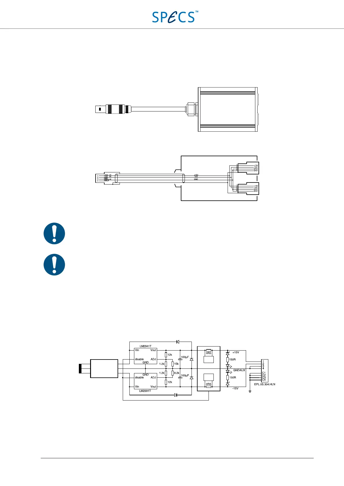
Connection using Y-splitter
The Y-splitter (optional item) allows two instruments to be powered from the auxiliary power supply connector. The
two output connectors of the Y-splitter are wired in parallel, and the Y-splitter is inserted between the SC5 and the
instruments to be powered. The Y-splitter is shown in the picture below.
Figure 18: SC5 auxiliary power supply Y-splitter.
The schematic of the splitter is shown below:
Figure 19: Schematic of the Y-splitter for the auxiliary power supply.
Note: Make sure that the sum of current consumption of the two instruments connected to the AUX
power supply output of the SC5 over the Y-splitter does not exceed 300 mA.
Large power consumption from the auxiliary power supply will increase the temperature of the
SC5 due to additional thermal dissipation of the power supply. Make sure that the SC5 is operated
within the specified temperature range
and that there is enough space for airflow around the
instrument.
Schematic and connector pin layout
A schematic of the auxiliary power supply is shown in the picture below.
Figure 20: Schematic of the auxiliary power supply.
The auxiliary power supply is fed by a dedicated winding of the main power transformer. The unregulated part uses
ultrafast soft-recovery diodes for rectification followed by a large capacitor reservoir. The following two low-noise,
low drop-out regulators can be disabled by the overcurrent detection circuit if the current should exceed ±300 mA.
The two status LEDs (8) indicate whether the output voltage of the power supply is ±15 V (LEDs on), the device
Unregulated
power supply
Overcurrent
detection
PE