SC5 Signal Conversion Performance Measurements
64
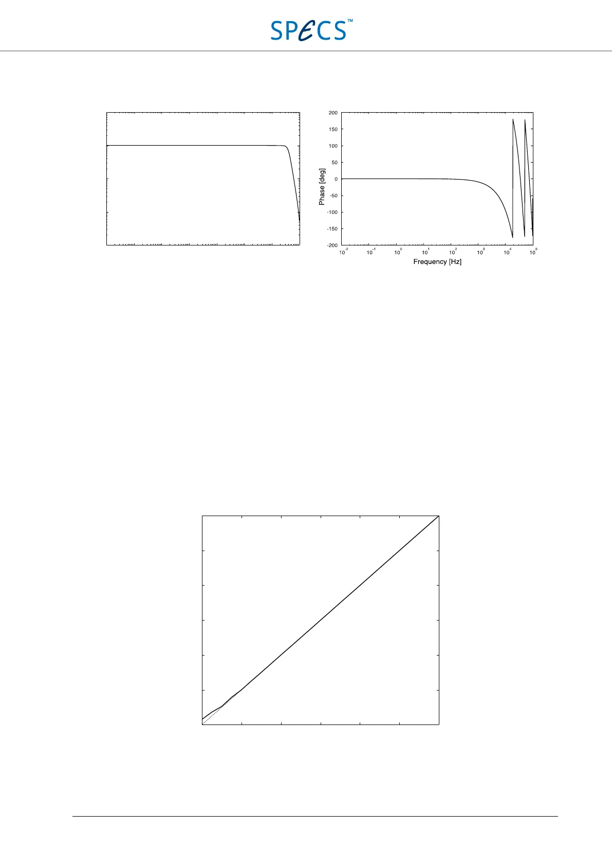
Figure 44: Output to input transfer function amplitude (left) and phase (right) from 10 mHz to 100 kHz, including all
delays due to digital signal processing.
Linearity
Linearity is measured with a National Instruments 4071 PXI digital multimeter operated in digitizer mode at 5 kS/s
connected to AO1. The sinewave has a frequency of 100 Hz and amplitudes ranging from 10 V (0 dBFS) to 10 µV (-
120 dBFS). The following settings were used for the measurement:
DMM
Measured output: AO1 Mode of operation: Digitizer, AC volts
Output signal: Sine wave Range: 10 V and 100 mV
Frequency: 100 Hz Sampling rate: 5 kS/s
Resolution: 18 bit
Figure 45: Linearity of the analog outputs of the SC5. The dotted line corresponds to ideal linearity.
10
1
10
0
10
-1
10
-2
10
2
10
3
10
4
10
5
10
−3
10
−2
10
−1
10
0
10
1
Output to input voltage [V]
Frequency [Hz]
-120 -100 -80 -60 -40 -20 0
Set amplitude [dBFS]
Output amplitude [dBFS]
0
-20
-40
-60
-80
-100
-120