Component Testing Procedures
Component Testing Procedures
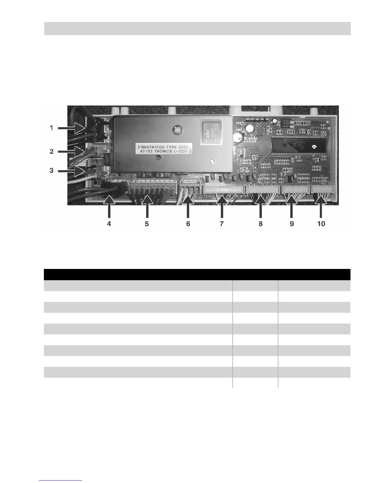
Connector Locations on the Module Board
Component Connector Fault Code(s)*
1. Door Switch CNJ N/A
2. Power in from Surge Protector CNK N/A
3. Pressure Switch CNI F04, F05, F10, F14
4. Heating Element CNH F15
5. Main Motor CNG F01, F02
6. Pump / Fan Motor CNF F05, F11, F13
7. Water Valves CNE N/A
8. Push Buttons, Dry Time/Water Temp. Selectors CNC F08
9. Cycle Selector CND F06
10. NTC Sensors / LED’s CNB F03, F13
* For more information about how to read Fault Codes and what they mean, see the “Fault Code Chart”
(Continued on the next page)
The following tests are performed by taking ohm readings on the Module Board connections listed below.
The Module Board can be accessed once the back panel has been removed. See “Component Access Locations.”