7.2 Power supply
The B-U585I-IOT02A Discovery kit board is designed to be powered by a 5 V DC power supply. It is possible
to configure the B-U585I-IOT02A Discovery kit using the JP4 jumper to select any of the four following power
sources: 5V_USB_STLK, 5V_VIN, 5V_UCPD, 5V_VBAT, and 5V_USB_CHGR.
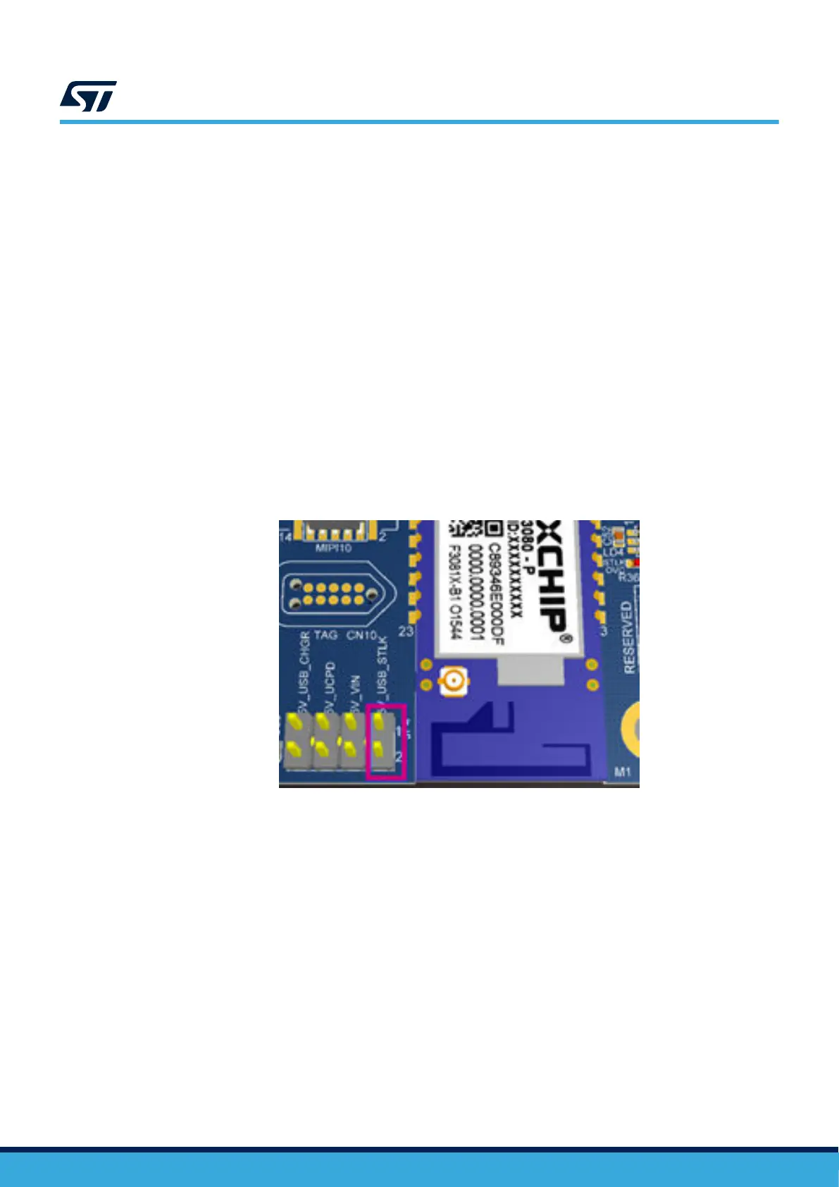
5V_USB_STLK: JP4 [1-2]
(Refer to Figure 10)
This is a 5 V DC power from the CN8 STLINK-V3E USB connector. This is the default setting. If the
USB enumeration succeeds, the 5V_USB_STLK power is enabled, by asserting the T_PWR_EN signal (from
STM32F723IEK). This pin is connected to an STMPS2151STR power switch, which powers the board. This
power switch also features a current limitation to protect the PC in case of an onboard short circuit (the current is
higher than 500 mA). The B-U585I-IOT02A Discovery kit can be powered from the CN8 ST-LINK USB connector,
but only the ST-LINK circuit has the power before USB enumeration because the host PC only provides 100
mA to the board at that time. During the USB enumeration, the B-U585I-IOT02A Discovery kit asks for 500
mA power to the host PC. If the host can provide the required power, the STMPS2151STR power transistor
is switched ON, and the LD3 red LED is turned ON, thus the B-U585I-IOT02A Discovery kit can consume
up to 500 mA current, but no more. If the host cannot provide the requested current, the enumeration fails.
Therefore, the STMPS2151STR remains OFF and the MCU part including the extension board is not powered.
As a consequence, the LD3 red LED remains turned OFF. In this case, it is mandatory to use an external power
supply.
Figure 10. JP4: 5V_USB_STLK selection
5V_VIN: JP4 [3-4]
(Refer to Figure 11)
This is the 7 to 12 V DC power from ARDUINO
®
CN17 pin 8 (named VIN on ARDUINO
®
connector silkscreen). In
this case, the JP4 jumper must be fitted between pin 3 and pin 4 to select the 5V_VIN power source. In this case,
the DC power comes from the power supply through the ARDUINO
®
Uno V3 battery shield (compatible with the
Adafruit PowerBoost 500 shield).
UM2839
Power supply
UM2839 - Rev 4
page 15/54