7.1.4 Using an external debug tool to program and debug the on-board STM32
There are two basic ways to support an external debug tool:
1. Keep the embedded STLINK-V3E running. Power on the STLINK-V3E at first until the COM LED lights RED.
Then connect the external debug tool through the CN9 MIPI10 debug connector.
2. Set the embedded STLINK-V3E in a high-impedance state. When the jumper JP1 (STLK_RST) is set ON,
the embedded STLINK-V3E is in the RESET state, and all GPIOs are in high impedance. Then the user can
connect his external debug tool to the CN9 debug connector or the CN10 TAG connector.
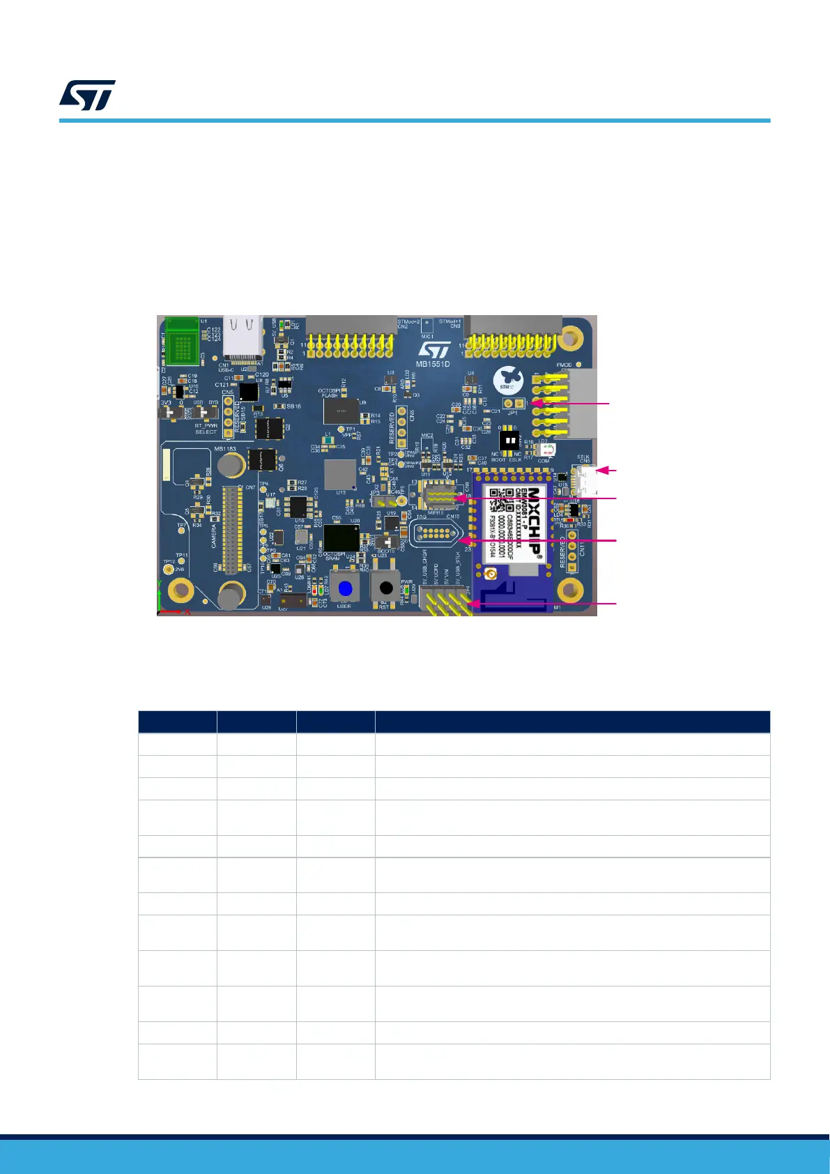
Figure 7. Connecting an external debug tool to program the on-board STM32
DT55057V1
ST-LINK USB connector
(CN8)
ST-LINK reset jumper
(JP1)
Debug connector to connect
to external tool
(CN9)
TAG connector
(CN10)
Power supply selection
(JP4)
Table 4 describes the CN9 STDC14/MIPI10 debug connector pinout.
Table 4. CN9 STDC14/MIPI10 debug connector pinout
MIPI10
STDC14 pin CN9 Designation
- 1 NC Reserved
- 2 NC Reserved
1 3 T_VCC Target VCC
2 4 T_SWDIO
Target SWDIO using SWD protocol or Target JTMS (T_JTMS) using JTAG
protocol
3 5 GND Ground
4 6 T_SWCLK
Target SWCLK using SWD protocol or Target JCLK (T_JCLK) using JTAG
protocol
5 7 GND Ground
6 8 T_SWO
Target SWO using SWD protocol or Target JTDO (T_JTMS) using JTAG
protocol
7 9 T_JRCLK
Not used by SWD protocol, Target JRCLK (T_JRCLK) using JTAG protocol,
only for specific use
8 10 T_JTDI
Not used by SWD protocol, Target JTDI (T_JTDI) using JTAG protocol, only
for external tools
9 11 GNDDetect GND detection for plug indicator, used on SWD and JTAG
10 12 T_NRST
Target NRST using SWD protocol or Target JTMS (T_JTMS) using JTAG
protocol
UM2839
Embedded STLINK-V3E
UM2839 - Rev 4
page 13/54