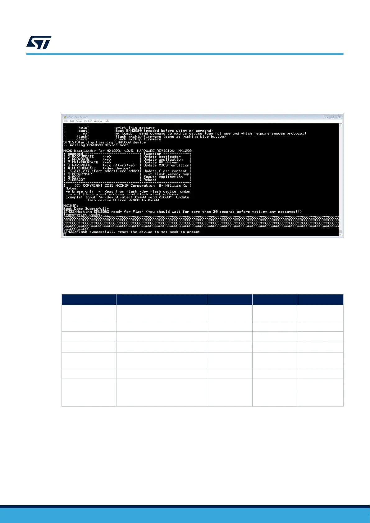
• Wait until the end of the flash procedure. The green LED flashes quickly while flashing, slowly when the
flash procedure is over and successful. A red LED means failure.
The check command on the console might check if the flash procedure is correct. If the user has not seen any
issue during the process, Figure 23 shows completion without error messages.
Figure 23. Firmware update utility successful completion
7.9 MEMS
Several STMicroelectronics MEMS modules are available on the B-U585I-IOT02A Discovery kit board all
connected on I2C2 (PH4, PH5).
Table 15. I
2
C addresses for MEMS
Module
Description SAD[7:0] + R/W
I
2
C write address I
2
C read address
HTS221
Capacitive digital sensor for relative
humidity and temperature
1011111x 0xBE 0xBF
IIS2MDCTR 3-axis magnetometer
0011110x 0x3C 0x3D
LPS22HH MEMS nano pressure sensor
1011101x 0xBA 0xBB
ISM330DHCX 3D accelerometer and 3D gyroscope
1101011x 0xD6 0xD7
VL53L5CXV0GC/1
Time-of-Flight ranging and
gesture‑detection sensor
0101001x 0x52 0x53
STSAFE-A110 Authentication and security
0100000x 0x40 0x41
VEML6030/VEML3235
Ambient light sensor. On the IoT
board, VEML6030 (BU585IIO2A$GTx)
or VEML3235 (BU585IIO2A1$GTx) is
mounted.
0010000x 0x20 0x21
7.9.1 Two on-board MEMS audio sensor omnidirectional digital microphones (MP23DB01HPTR)
The B-U585I-IOT02A Discovery kit provides two MP23DB01HP digital MEMS microphones. The microphones are
connected to the MCU's ADF/MDF interface. The clock needs to be configurated accordingly. The I/O interface is
described in Table 16.
UM2839
MEMS
UM2839 - Rev 4
page 28/54