7.3 Clock source
The board is designed with two crystals:
• X1: Crystal for the STM32U585AI HSE clock inputs. This component is optional and not fitted by default.
• X2: 32.768 kHz crystal for the STM32U585AI LSE clock inputs
Table 6. I/O configuration for the optional HSE
I/O
Solder
bridge
Setting Configuration
PH0 SB5
ON PH0-OSC_IN is connected to STLK_MCO 8 MHz.
OFF
PH0-OSC_IN terminal is not connected to STLK_MCO.
PHO OSC_IN is connected to the 16 MHz HSE crystal.
PH1 SB4
ON PH1 is used as GPIO MEMs enable.
OFF PH1 OSC_OUT is connected to the 16 MHz HSE crystal.
7.4 MCU management
7.4.1 Reset sources
The active LOW reset sources are:
• The B2 reset button
• The reset signal coming from CN17 pin 3
• The reset signal coming from ST-LINK
7.4.2 MCU boot switch and jumper for current measurement
Table 7. MCU jumper and switch
Reference
Name Comment
JP3 Jumper
Jumper for MCU current measurement
The MCU current measurement can be performed on JP3.
By default, a jumper is placed on JP3.
For the current measurement configuration, an ammeter must replace the JP3
jumper.
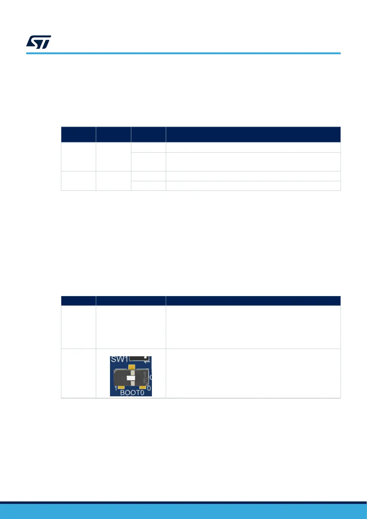
SW1
Switch
BOOT0 MCU‑boot mode selection. Refer to the MCU specification for more
details.
UM2839
Clock source
UM2839 - Rev 4
page 19/54