7.8.2
Bluetooth
®
Low Energy module firmware update
The Bluetooth
®
Low Energy module firmware can be updated using the onboard ST-LINK that can be connected
directly to the Bluetooth
®
Low Energy debug port (SWD port), by setting the SW5 switch to ON and switching
SW4 to OFF. Another way is to connect an external ST-LINK directly to the CN5 SWD interface to update the
module.
The STM32WB5MM module is shipped with the BLE_MultiAppAt application available in the STM32CubeWB
MCU Package for STM32WB series.
Using the CN5 SWD interface or CN12 USB connector shown below, the Bluetooth
®
Low Energy module
firmware can be updated.
The STM32WB5MM module is shipped with the following option bytes: nSWBOOT0=0, nBOOT0=1, and
nBOOT1=1. So, as default, the BOOT0 pin is not used and the nBOOT0/nBOOT1 options bytes are used.
Note: The BOOT0 pin of the STM32WB chip is pulled down within the module, even if there is no pull-down outside
the module, the STM32WB might boot on system flash if nSWBOOT0=1.
To program an application in the WB module an external ST-LINK interface is required, and debug signals must
be connected to CN5. Pin 1: Target VCC, pin 2: SWCLK, pin 3: GND, and pin 4: SWDIO.
The STM32WB5MM module can also be programmed using the CN12 USB connector, but option bytes must be
set as follows: SWBOOT0=0 and nBOOT0=0. This way the STM32WB boots on the flash system allowing it to
flash using the USB port.
For more information about how to flash the STM32WB chip (FUS and wireless stack), refer to the Release_Not
es.html file available in the STM32CubeWB MCU Package under the Projects\STM32WB_Copro_Wireless
_Binaries\STM32WB5x directories.
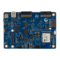
Figure 17. Bluetooth
®
Low Energy module firmware update port
DT55109V1
USB type-C
®
(CN1)
STM32WB5MMG
Bluetooth
®
module
(U1)
Bluetooth
®
module
debugging
connector
(CN5)
Bluetooth
®
module
power selection
(SW3)
Bluetooth
®
BOOT0
selection
(SW6)
Bluetooth
®
module
USB (CN12)
Bluetooth
®
module reset
(B1)
Table 12. Bluetooth
®
Low Energy module I/O configuration
MCU I/O
Configuration
PG6 PA0 (WRLS.WKUP_B)
PC11 (UART4_RX) PA2 (WRLS.UART4_RX)
PC10 (UART4_TX) PA3 (WRLS.UART4_TX)
UM2839
RF modules
UM2839 - Rev 4
page 24/54

 Loading...