7.12 STMod+ connector
On the B-U585I-IOT02A Discovery kit node board, there are two STMod+ connectors, to support flexibility in
small form factor applications. The STMod+ connector extends SPI, UART, and spare I/Os for different peripheral
expansions like cellular modems.
Pin assignment is based on the existing STMod+ standard.
A switch is used to select either UART or SPI from the MCU to the STMod+ connector. The CN3
STMOD+.UART2_SPI1_SEL (PH13 I/O) and CN2 STMOD+.UART3_SPI3_SEL (PH15 I/O) are used for
selection. Set these I/Os to HIGH to select UART or LOW to select SPI.
Caution:
CN4 Pmod
™
and CN3 STMod+ cannot be used at the same time because they share the same signals.
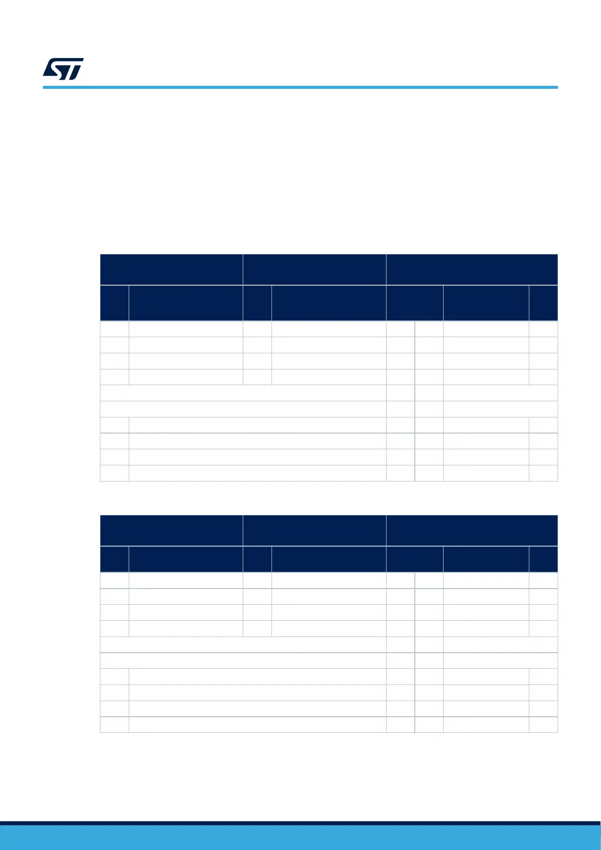
Table 25. CN2 STMod+ connector mapping
Alternate configuration (UART)
PH15 set HIGH
Standard configuration (SPI)
PH15 set LOW
-
STM3
2U5
pin
Pin name
STM3
2U5
pin
Pin name
STMod+pin
number
Pin name
MCU
pin
PD11 STMOD+.2_UART3_CTS PG12 STMOD+.2_SPI3_NSS 1 11 STMOD+.2_INT PE6
PD8 STMOD+2_UART3_TX PD6 STMOD+.2_SP31_MOSI 2 12 STMOD+.2_RST PB13
PD9 STMOD+.2_UART3_RX PG10 STMOD+.2_SPI3_MISO 3 13 STMOD+.2_ADC PG0
PD12 STMOD+.2_UART3_RTS PG9 STMOD+.2_SPI3_SCK 4 14 STMOD+.2_TIM PC9
GND 5 15 5V
5V 6 16 GND
PH4 I2C2_SCL 7 17 STMOD+.2_17 PG1
PC12 STMOD+.2_SPI3_MOSI_alt1 8 18 STMOD+.2_18 PD2
PB4 STMOD+.2_SPI3_MISO_alt1 9 19 STMOD+.2_19 PD5
PH5 I2C2_SDA 10 20 STMOD+.2_20 PG8
Table 26. CN3 STMod+ connector mapping
Alternate configuration (UART)
PH13 set HIGH
Standard configuration (SPI)
PH13 set LOW
-
MCU
pin
Pin name
MCU
pin
Pin name
STMod+pin
number
Pin name
MCU
pin
PA0 STMOD+.1_UART2_CTS PA4 STMOD+.1_SPI1_NSS 1 11 STMOD+.1_INT PE4
PA2 STMOD+.1_UART2_TX PE15 STMOD+.1_SPI1_MOSI 2 12 STMOD+.1_RST PG7
PA3 STMOD+.1_UART2_RX PE14 STMOD+.1_SPI1_MISO 3 13 STMOD+.1_ADC PA5
PA1 STMOD+.1_UART2_RTS PE13 STMOD+.1_SPI1_SCK 4 14 STMOD+.1_TIM PE5
GND 5 15 5V
5V 6 16 GND
PB8 I2C1_SCL 7 17 STMOD+.1_17 PE2
PG4 STMOD+.1_SPI1_MOSI_alt1 8 18 STMOD+.1_18 PD0
PG3 STMOD+.1_SPI1_MISO_alt1 9 19 STMOD+.1_19 PF5
PB9 I2C1_SDA 10 20 STMOD+.1_20 PB14
UM2839
STMod+ connector
UM2839 - Rev 4
page 34/54