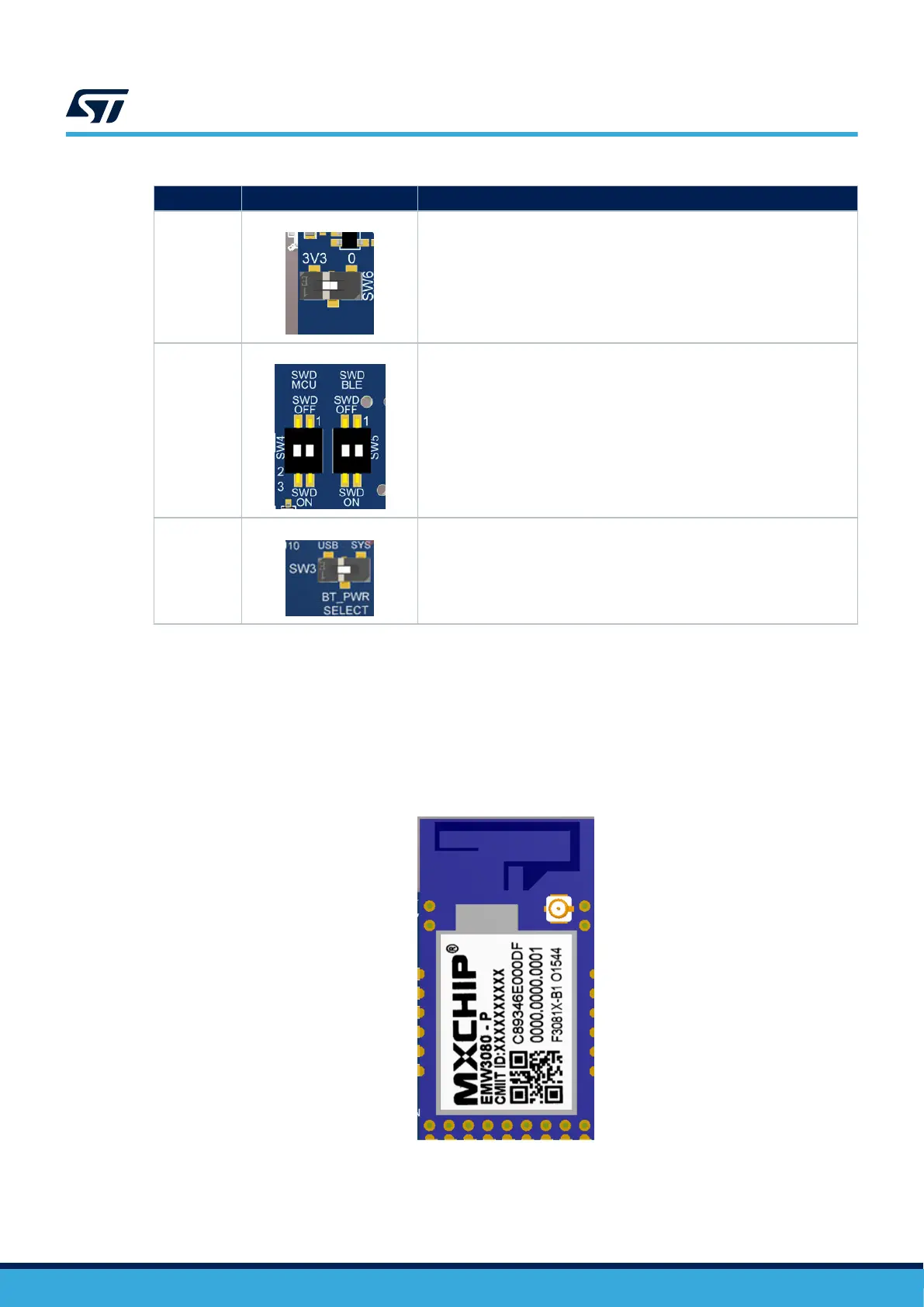
Table 13. Bluetooth
®
Low Energy power selection
Reference Name Comment
SW6
BOOT0 switch
Switch to select the Bluetooth
®
Low Energy module Boot mode. By default
this switch is set to 0.
SW4, SW5
Debug switch
Switch used to connect the onboard ST-LINK to the Bluetooth
®
module debug
port. By default, ST-LINK is connected to the target MCU. Both switches must
not be ON at the same time.
To connect the onboard ST-LINK to the Bluetooth
®
module, set SW4 OFF and
SW5 ON.
SW3
Power switch
Bluetooth
®
module power selection
This switch chooses to power the Bluetooth
®
module using the 3.3 V coming
from the system or the Bluetooth
®
module USB connector, in case of
debugging or flashing.
Put the switch on the SYS position to select the system power.
7.8.3
MXCHIP EMW3080 (802.11 b/g/n compliant Wi‑Fi
®
module)
The M1 MXCHIP EMW3080 module is implemented on the top side of the B-U585I-IOT02A Discovery kit
board. This module is an embedded wireless internet connectivity device. The module uses the SPI (SPI2 of
STM32U585AI) interface to communicate with the MCU. The Wi‑Fi
®
module requires no operating system and
has a completely integrated TCP/IP stack that only requires AT commands to establish connectivity.
This module complies with FCC/CE certification.
Figure 18. EMW3080 module
UM2839
RF modules
UM2839 - Rev 4
page 25/54