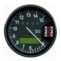
Installation ST700 Dash Display System
10
approved Stack agent for details of wiring harness extensions. Labels
identify each wire in the harness shown in Figure 3.
1. Identify all the relevant connectors of the wiring harness.
2. Plan the location of all the component parts of your ST700 Dash Dis-
play System and decide the best layout to use when you install the
wiring harness.
Note that your installation might not use all the cables that exist in the
harness. You should tie back and protect all unused connectors.
3. Begin at the instrument panel where you will install the ST700 Dash
Display System display. Lay the wiring harness into the vehicle,
with the cable branches running to their appropriate locations.
Allow sufficient slack in the harness so that you can connect it to the
ST700 Dash Display System before you insert the display into the
instrument panel.
You should route all cables to be no closer than 75 mm (3 inches) to
the ignition HT leads or the distributor cap. Do not run cables close to
sources of intense heat.
4. Fit cable glands to protect the cables where they pass through bulk-
heads or panels. This is particularly important when you pass cables
through carbon fibre partitions, which can wear through them eas-
ily.