– 47 –
13
25
1
14
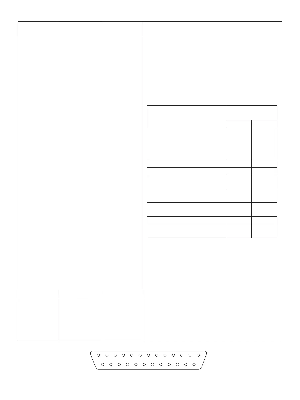
D-sub 25 Pin
PinNo.
Signal
name
Direction Function
2)ESC/POSMode
A) DTR/DSR communication mode
Indicates whether data receive from host is enabled or
disabled.
Space: Receive enabled
Mark: Receive disabled
e busy condition can be changed by using Memory
switch as follows:
Printerstatus
MemorySW
4-4
OFF ON
1. During the period from when
the power is turned on (includ-
ing resetting using the interface)
to when the printer is ready to
receive data.
BUSY BUSY
2. During the self printing. BUSY BUSY
3. When the cover is open. — BUSY
4. During the paper feeding by
FEED button.
— BUSY
5. When the printer stops printing
due to a paper-end.
— BUSY
6. During macro executing standby
status.
— BUSY
7. When an error has occurred. — BUSY
8. When the receive buer becomes-
full.
BUSY BUSY
B) X-On/X-O Communication Mode
Always space, except during following conditions:
• Period between reset and communication ena-
bled
• During self printing
21~24 N/C Not used.
25
INIT IN
When DIP Switch 3-8 = OFF;
Status of this signal is not checked.
When DIP Switch 3-8 = ON;
is is an externally reset signal.
A space above 1 ms pulse width engages reset.