– 51 –
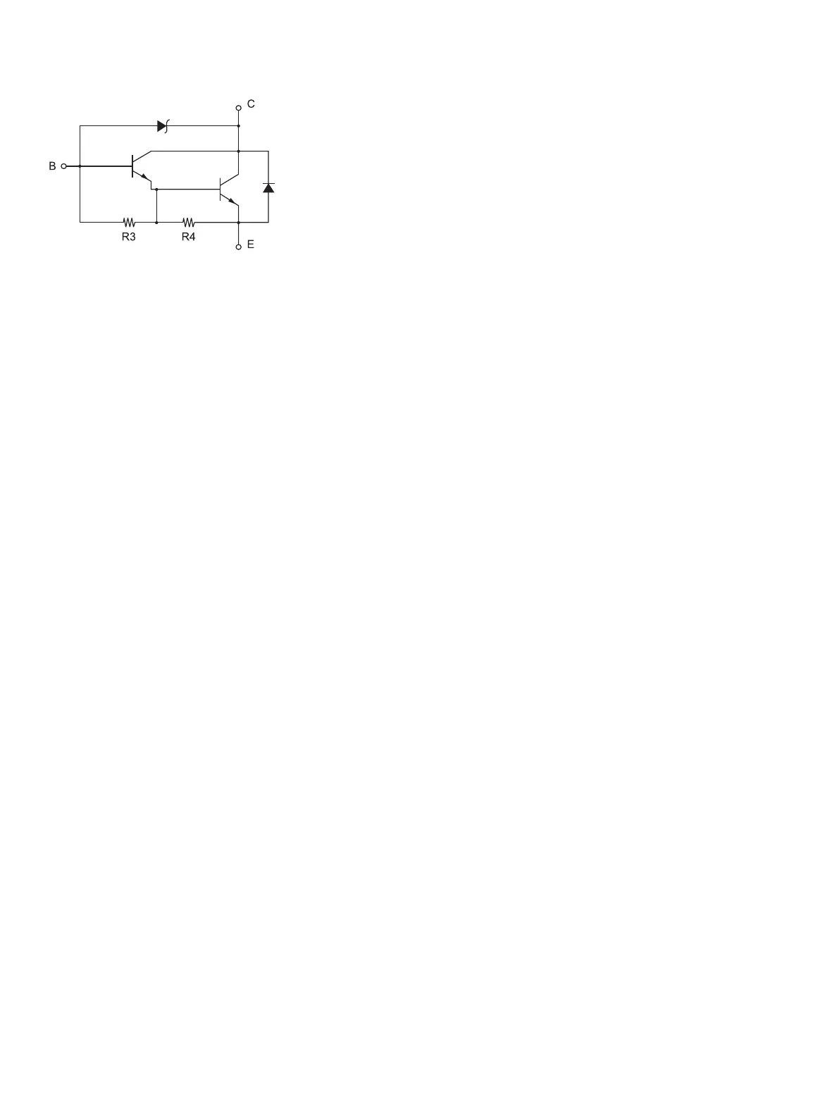
R3 = 3.5 kΩ
R4 = 300 Ω
Drive Output: 24 V, Max. 1.0 A
TR1, TR2: Transistor 2SD 1866 or equivalent
R1=10 kW
R2=33 kW
Reference
2SD 1866 Circuit Conguration
Notes:
1. Peripheral units 1 and 2 cannot be driven simultaneously. To drive them
continuously, set the duty cycle ratio to 20% or less (excluding an externally
connected buzzer).
2. e following external buzzer is available as an option.
External buzzer model: RMB-24
Voltage rating: 24V
Average consumption current: Max. 21 mA (at 24V)
Sound pressure: Min. 75 dB at 1 m
Lead wires: red (+) black (-)
3. Never use the external buzzer command if you connect a device (such as a
cash drawer) other than an external buzzer. It could damage the connected
device and the printer circuit. Refer to the separate Programmer's Manual for
details on commands.
4. e status of the compulsion switch can be known from the status command.
Refer to the separate Programmer's Manual for details.
5. Minimum resistance for coils L1 and L2 is 24.
6. Absolute maximum ratings for diodes D1 and D2 (Ta = 25°C) are:
Average Rectied Current I
o
= 1A
7. Absolute maximum rating for transistors TR1 and TR2 (Ta = 25°C) are:
Collector current I
C
= 2.0 A