62
EN
After the scan process is complete, you will be prompted to specify the storage
location and name for the created le. Your point cloud has now been created
and is ready for further processing. The le contains comma separated values
of coordinates in the order X, Y, Z.
11.600 , 4.850 , -0.406
11.600 , 4.850 , -0.350
11.600 , 4.850 , -0.284
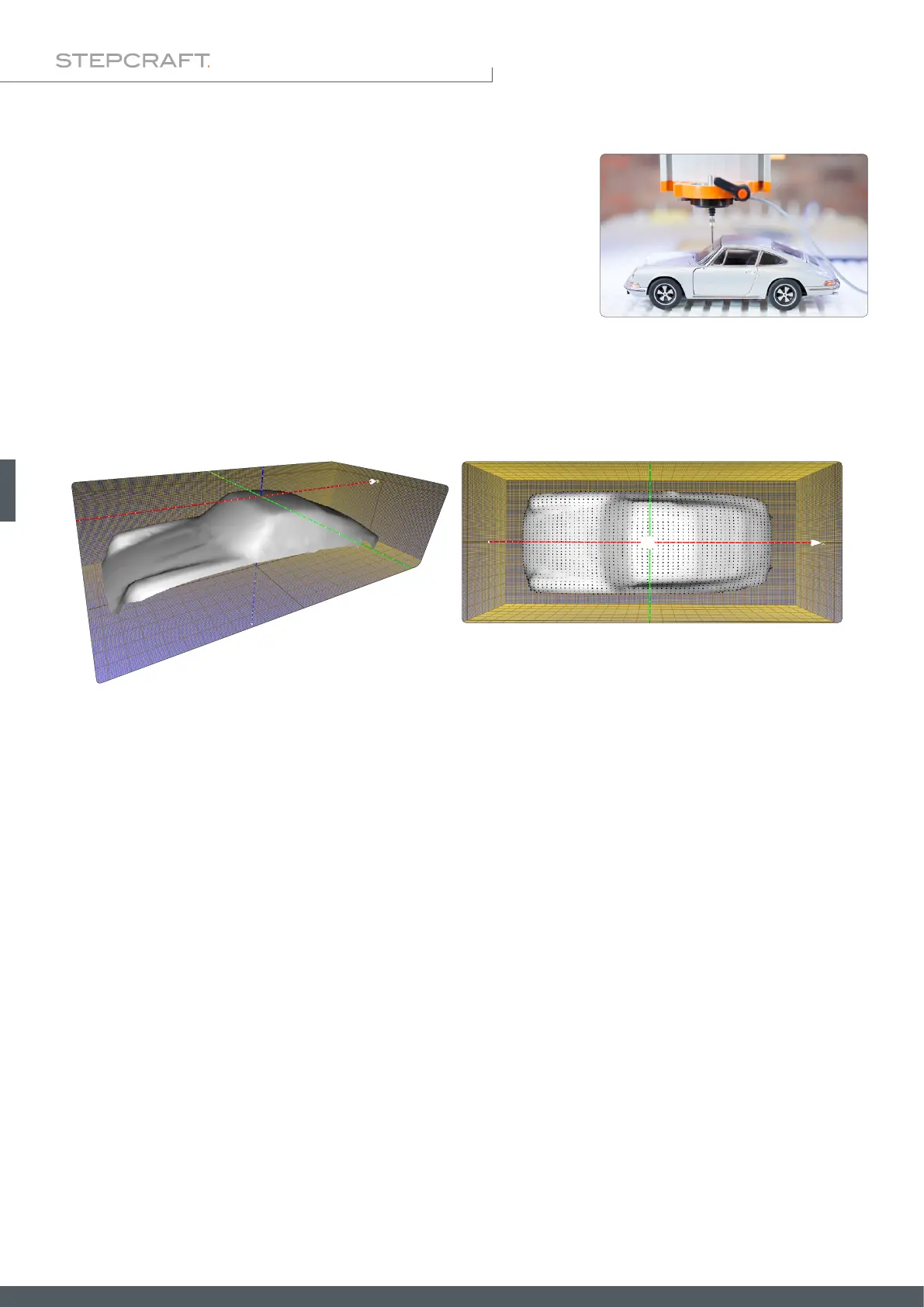
Depending on how you choose the display options, you might get a result similar to the one shown. Because of the nu-
merous options, it is recommended that you familiarize yourself in detail with the 3D software.
This illustration was achieved by using these options in the MeshLab software:
Render – Show Normal
Render – Show Curvature
Filters – Normals, Curvature and Orientation – Compute normal for point sets
Filters – Remeshing, Simplication and Reconstruction – Surface Reconstruction: Ball Pivoting
Filters – Remeshing, Simplication and Reconstruction – Close Holes.
For example, you can use this data to create an NC program by exporting the data as an STL and then loading it into a
software such as Autodesk Fusion 360, which allows you to generate an NC file from the data as usual.
You can then make use of the le using software such as MeshLab. You can export the model as an STL le or similar. If
you have questions about the respective software, please contact the manufacturer of it.
6.5.6 3D Cloud of Points – After Scanning