S - 108 | English English | S - 109
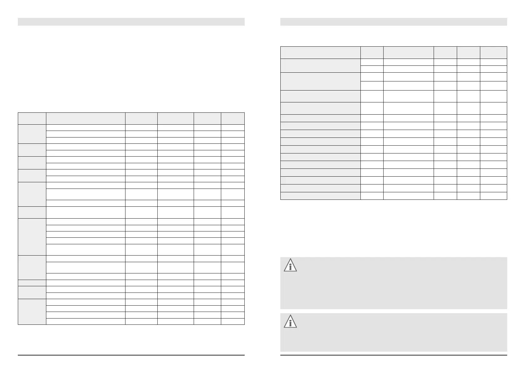
Recommended Torque Settings
All bolted connections of the bicycle components have to be tightened carefully and checked regularly to ensure
the safe and reliable operation of your STEVENS bicycle. This is best done with a torque wrench that disengages at
the desired torque value or a click-type torque wrench. Tighten carefully by approaching the prescribed maximum
torque value in small steps (0.5 Nm increments) and check in between the proper fit of the component. Do not
exceed the maximum torque value indicated by the manufacturer!
Where no maximum torque value is given start with 2Nm. Observe the indicated values and observe the values
on the components themselves and/or in the instructions of the component manufacturers.
Component Bolted connections Shimano
1
(Nm)
SRAM/Avid
2
(Nm)
Tektro
3
(Nm)
TRP
4
(Nm)
Rear
derailleur
Mount (on frame/derailleur hanger) 8–10 8–10
Cable clamp 5–7 4–5
Pulley wheels 3–4
Front
derailleur
Mount on frame 5–7 5–7
Cable clamp 5–7 5
Shifter Mount on handlebars 5 2.5–4
Hole covering 0.3–0.5
Brake lever
unit
Mount on handlebars 6–8 5–7 6–8
Time trial brake lever 5–7
Hub Quick-release lever 5 –7. 5
Locknut for bearing adjustment of
quick-release hubs
10–25
Sprocket cluster lock ring 29–49 40
Internal gear
hub
Axle nut 30–45
Crank Crank mount (grease-free square-head) 35–50
Crank mount (Shimano Octalink) 35–50
Crank mount (Shimano Hollowtech II) 12–15
Crank mount (Isis) 31–34
Chainring mount 8–11 12–14 (steel)
8–9 (alu)
Sealed
cartridge
bearing
Shell (square-head) 49–69
Shell
(Shimano Hollowtech II, SRAM Gigapipe)
35–50 34–41
Octalink 50–70
Pedal Pedal axle 35
Shoe Cleat 5–6
Spike 4
Brake
(V-brake)
Cable clamp 6–8 6–8 6–8 6–8
Brake shoe mount 6–8 6–8 6–8 6–8
Brake pad fixing 1–2
Brake boss frame/fork 8–10
1
si.shimano.com
2
sram.com
3
tektro.com
4
trpbrakes.com
Note:
Due to the unmanageable number of components on the market, STEVENS is not in a position to foresee
every product that will be replaced or newly assembled by third parties. Therefore STEVENS denies any
liability for such kind of additions or modifications with regard to compatibility, torque values etc. Whoever
assembles or modifies the STEVENS bicycle shall ensure that the bicycle is assembled according to the
state-of-the-art in science and technology.
Note:
Some components have the maximum permissible torque values printed on them. Use a torque wrench
and do not exceed the maximum torque values! If you are in doubt or if you have any questions, contact
your STEVENS dealer.
Recommended Torque Settings for Disc Brakes and Hydraulic Rim Brakes
Component Shimano
1
(Nm)
Avid
2
(Nm)
Tektro
3
(Nm)
TRP
4
(Nm)
Magura HS
5
(Nm)
Brake calliper mount on frame/fork 6–8 9–10 (IS-Adapter) 6–8 6–8 6
8–10 (brake calliper)
Brake lever unit on handlebar
– Single-bolt clamp
– Two-bolt clamp
6–8 5–7 4
7 (carbon)
Union screws of hose at grip
and normal hose at brake calliper
5–7 5 4
Brake hose connector at
brake calliper (disc tube hose)
5–7
Expansion tank cap 0.3–0.5
Bleeding device brake calliper 4–6 4–6
Bleeding device brake lever 2–4
Brake rotor fixing (6-holes) 4 6.2 4–6 6–8
Brake rotor fixing (Centerlock) 40
Hose (union nut) direct connection 5–7 5–7
Slave cylinder (bleeder screw) 4–6 4–6
Hose (union nut) direct connection 4
Slave cylinder (bleeder screw) 4
Brake pad retainer at brake calliper 3–5
Cable clamp at brake calliper 4–6
1
si.shimano.com
2
sram.com
3
tektro.com
4
trpbrakes.com
5
magura.com
These values are reference values of the above-mentioned component manufacturers. Observe the values in the
instructions of the component manufacturers.
These values do not apply to the components of other manufacturers.