39GS 461
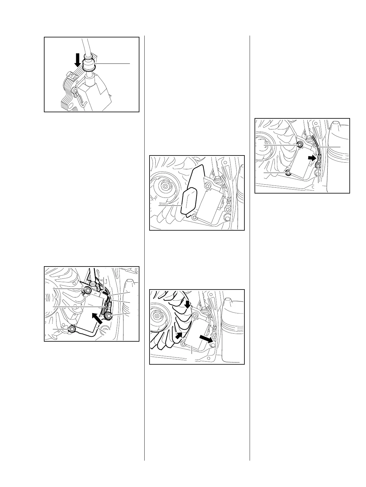
– Before twisting in the ignition
lead, fill the high-voltage output
with STIHL multi-purpose
grease, b 12
Do not use either graphite grease or
silicone insulating paste.
– Screw the ignition lead into the
ignition module – protective tube
and grommet must be pressed
onto ignition lead
: Push on the grommet (1)
Grommet (1) must be pushed on
fully to avoid faults on the ignition
system caused by dirt or moisture.
The short circuit wire and ground
wire are run below the ignition lead
: Position ignition module (1) and
insert screws (2)
– do not tighten
3443RA186 TG
1
2411RA056 TG
3
4
1
7
2
2
6
5
: Position ground wire (3) and
insert screw (4)
– do not tighten
: Fit connector (5) of short-circuit
wire (6) with the crimped side
facing the ground wire
: Press short-circuit wire (6) into
the cable holder (7) so that there
is no tensile load
– Connector tab and blade
receptacle must run parallel to
the edge of the ignition module
: Push back ignition module and
slide setting gauge (1)
1111 890 6400 between the legs
of the ignition module and the
magnetic pole of the flywheel
Shown without setting gauge for a
better view.
: Push back ignition module (1)
and hold in place – flywheel must
turn freely
2411RA057 TG
1
N
S
2411RA058 TG
1
: Turn the flywheel until the raised
part of the magnet poles (arrows)
is on the ignition module
– Setting gauge is pressed in
during the process
: Press and hold the ignition
module (1) against the setting
gauge
: Tighten screws (1) and pull out
setting gauge
: Align cable lug (arrow) of the
ground wire (2) so that the
distance to the blade receptacle
and housing wall is the same,
hold in place and tighten
screw (3)
– Check correct functioning
– Turn the flywheel: it must not
touch the ignition module
N
S
2411RA059 TG
2
3
1
1

 Loading...