40 GS 461
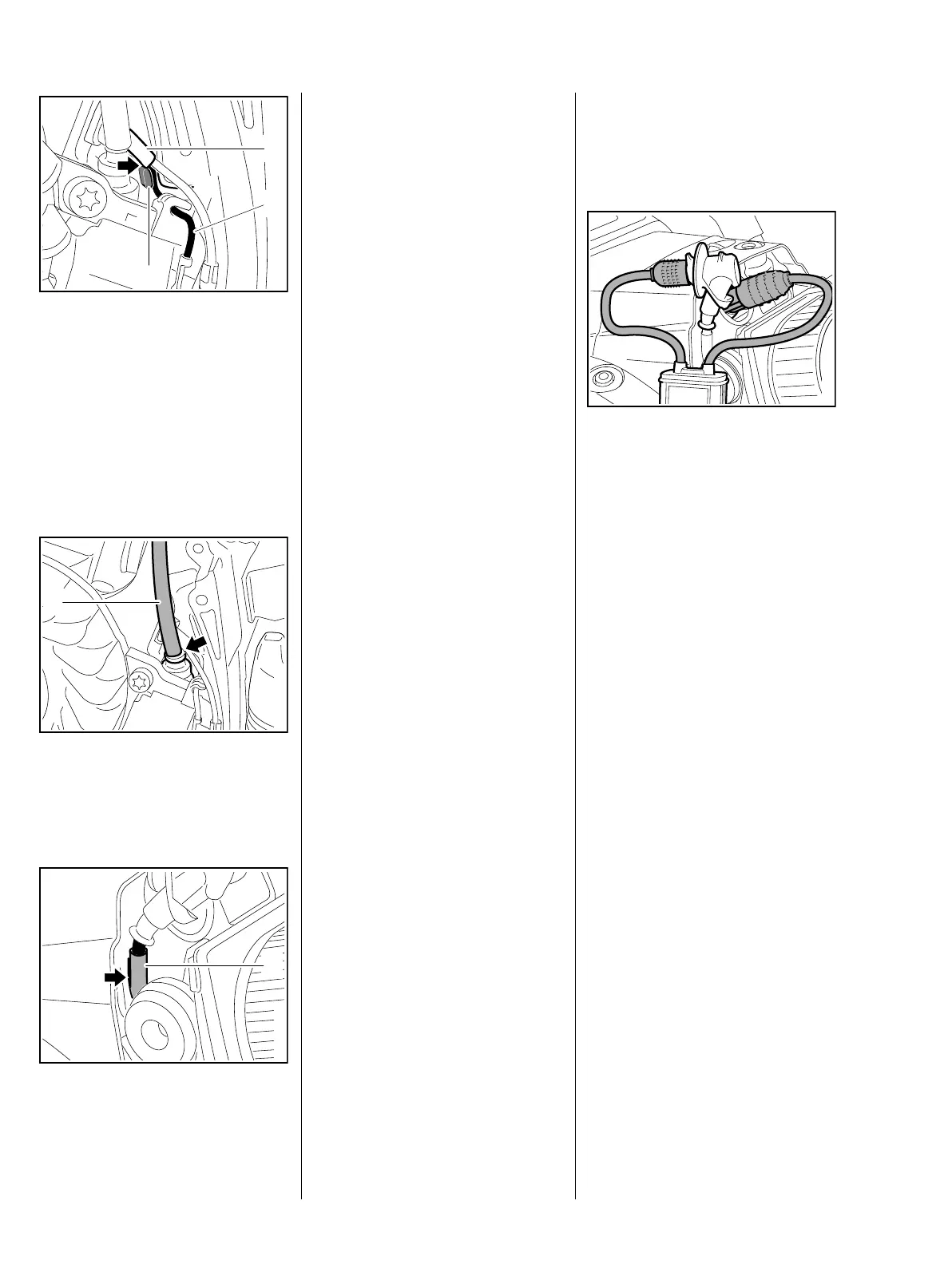
The compensation for longitudinal
movement of the short-circuit
wire (1) is between the crankcase
and the cable holder of the ignition
module
: Press short-circuit wire (1) into
the guide (2) – the protective
tube (3) must be flush with the fin
(arrow)
: Position insulating tube (1) so
that it
rests against the grommet
(arrow)
Protective tube (1) with ignition lead
must be in the guide (arrow) when
the shroud is fitted.
– Fit the shroud, b 5.4
3443RA202 TG
1
2
3
2411RA051 TG
1
3443RA194 TG
1
– Reassemble remaining parts in
reverse order
6.3 Testing the ignition
module
Before starting the test, install a new
spark plug.
The engine may start and
accelerate during the test.
– Test the ignition module using
either the ZAT 4 ignition system
tester 5910 850 4503 or the
ZAT 3 ignition system tester
5910 850 4520.
If a spark is visible, the ignition
system is in order.
– If no spark is visible in the spark
window, check the ignition
system with the aid of the
troubleshooting chart, b 6.7
The ignition test refers only to a
spark test, not to the ignition timing.
6.3.1 Testing the ignition
module with engine
analyzer MDG 1
The STIHL MDG 1 is used to easily,
reliably and quickly test the ignition
module.
The following is tested during the
test run:
– Ignition voltage
–Spark
– Short circuit
– Remove filter cover and air baffle
– secure air filter with slotted nut
– Before starting the test, check
spark plug, replace if necessary –
use only spark plugs
recommended by STIHL
: Install engine analyzer MDG 1
between spark plug and spark
plug boot
– Ground clips must rest against
the hexagon of the spark plug
– To diagnose the GS 461, select
"Other STIHL products". Then
start the "Diagnosis" function and
follow the steps of the diagnostic
software.
For an accurate result, crank the
engine quickly with the rewind
starter.
The engine may start and
accelerate during the test.
3443RA205 TG

 Loading...