58 GS 461
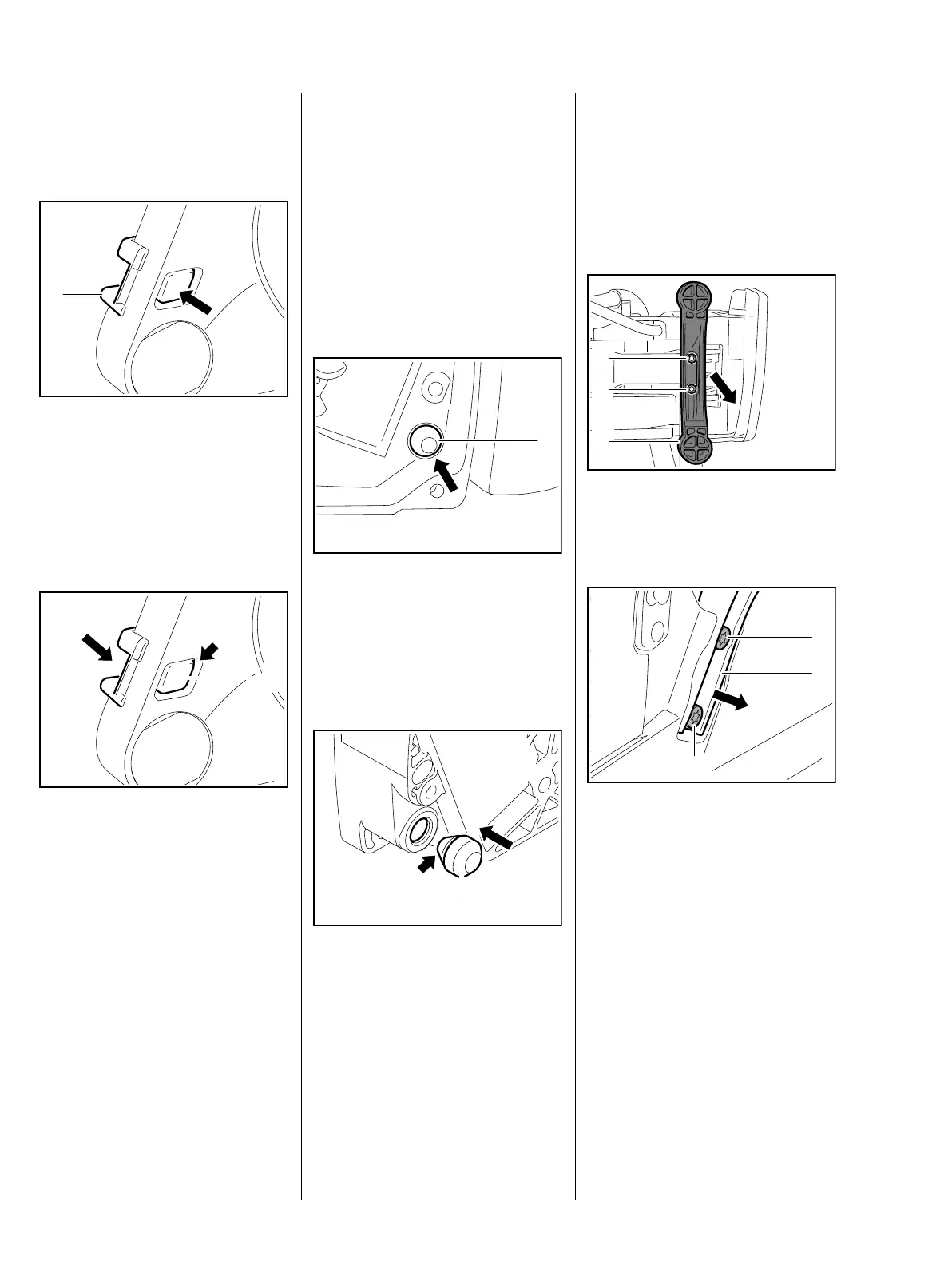
8.1.4 Stop buffer on clutch side
– Remove tank housing, b 10.8.3
: Press out stop buffer (1) from the
outside inwards
– Examine the stop buffer, replace
if necessary
Installation
: Align stop buffer so that the
peg (1) faces the opening (arrow)
of the tank housing
– Use STIHL press fluid to simplify
assembly, b 12
: Push stop buffer into the mount
and press the peg (1) into the
opening until it completely
encloses the opening (arrow)
3443RA346 TG
1
3443RA347 TG
1
– Reassemble remaining parts in
reverse order
8.1.5 Stop buffer on ignition
side
– Remove the ignition module,
b 6.2
– Remove tank housing, b 10.8.3
: Push the stop buffer (1) out
– Examine the stop buffer, replace
if necessary
Installation
– Use STIHL press fluid to simplify
assembly, b 12
: Align the stop buffer (1) with the
smaller conical pegs (arrow)
facing the crankcase and press
into the hole by turning slightly
1
2411RA088 TG3443RA349 TG
1
The conical peg must enclose the
hole completely on the ignition side.
– Reassemble remaining parts in
reverse order
8.2 Handlebar
: Remove screws (1) on the
bottom of the tank housing and
remove the support (2)
: Undo screws (1) and remove
handlebar (2)
Installation
– Coat screws for fastening the
handlebar with Loctite, b 12
1
2411RA089 TG
1
2
3443RA352 TG
1
1
2

 Loading...