22 HSE 61, HSE 71, HSE 81
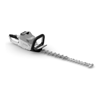
5.1.4 Assembling the
drive gear
: Place the O-ring (3) in the spur
gear.
: Fit the spur gear (1) on the cam
(4).
: Fit needle rollers (2) between the
hub and flats of cam (4).
2
3
1
4
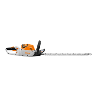
Important:
Before installing, check that the
carrier (1) is correctly positioned
in relation to the flat (A) (see
illustration) because the blade
brake will otherwise malfunction.
– Note the different installed
positions for the models (see
illustration).
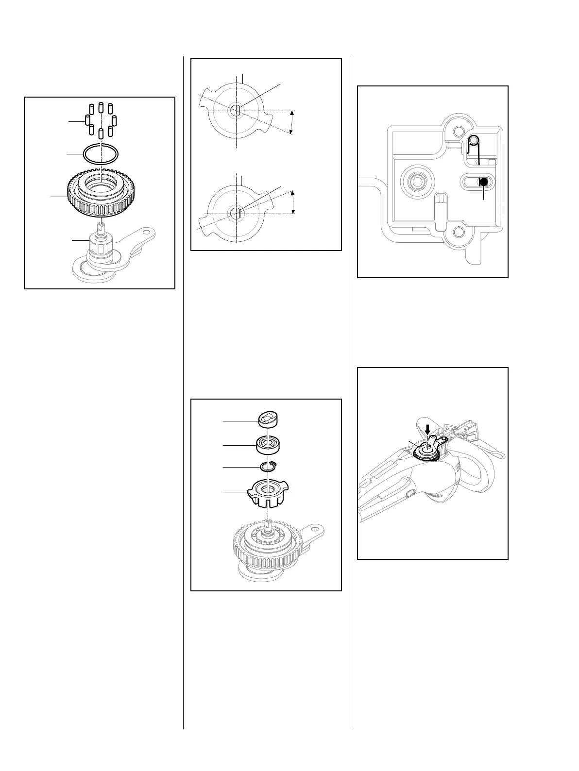
: Fit the carrier (1).
: Use pliers to fit the 12x1 circlip (2)
in the groove in the cam's stub.
: Push the bearing (3) into position.
: Fit the cam disk (4).
1
A
-22,5°
1
A
+22,5°
HSE 61
HSE 71, HSE 81
4
3
2
1
5.1.5 Installing the drive gear
: Check that the switch pin (1) is
properly installed in the control
unit.
– Install the switch pin, b 7.2.3.
: Push the drive gear (1) into the
housing until the bearing fits flush
in its seat.
– Mount the cutting attachment,
b 4.1.2.
1
1
 Loading...