Procedures
®
10MAY01
F2/3/8000-5
About the FDM 2000/
3000/8000
Overview of the Process
There are four main parts to the Stratasys modeling system:
• Slicing Software
• Computer Workstation
• FDM 2000/3000/8000 Modeler
• Modeling Materials
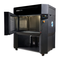
FDM 2000/3000/8000
The FDM 2000, FDM 3000, and FDM8000 use Fused Deposition Modeling
TM
(FDM) to turn computer-aided design (CAD) geometry into models that can be
used for design reviews, manufacturability stud-
ies, investment casting patterns, and marketing.
The FDM 2000 features the Break Away Support
System (BASS), allowing the designer to create
models with greater speed and precision. The
FDM 3000 features WaterWorks Soluble Release.
The support tip for the FDM 2000/3000/8000
extrudes a material that supports any overhang-
ing portions of the model’s geometry. With the
FDM 3000, when the model is completed, the
support is easily dissolved, leaving behind the
final product.
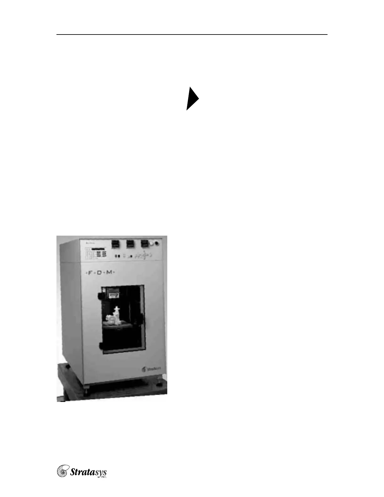
The FDM 2000/3000 is a bench-top unit standing
forty-five and one half inches high with a 26 x 36
inch footprint. Because it requires no exhaust hood
or other special facilities, it can be placed next to a
designer’s CAD workstation.
Each CAD file must be converted to an STL
format. The STL file is read into Stratasys’ slicing
software called Insight. Insight breaks the model
into individual slices, with each slice represent-
ing one layer of material. Insight then generates tool paths to fill the slices.
These toolpaths form the SML file.
After slicing an STL file and creating a Stratasys Modeling Language (SML)
file, the SML file is downloaded to the FDM Hardware for modeling.
About The FDM —Overview