*Note:
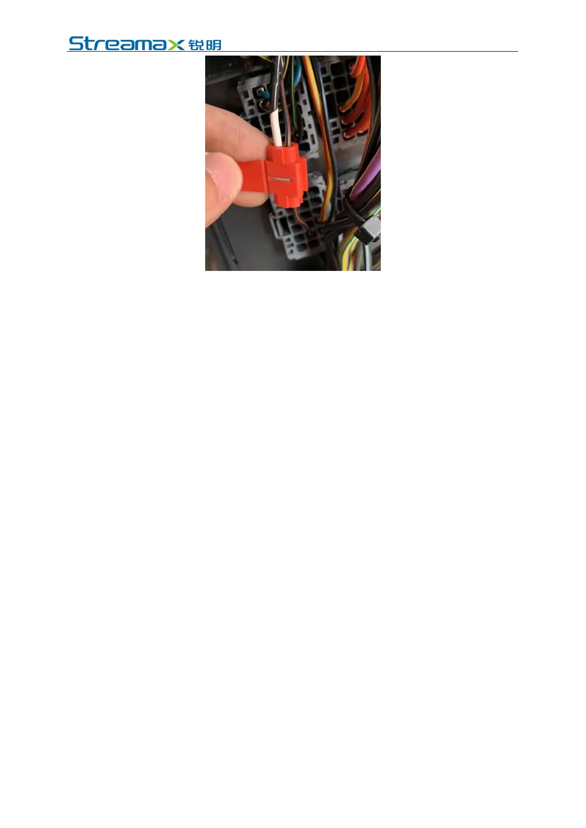
The power cable shall be connected using "special stripping-free connection
terminal" where possible (no stripping is required, so as to avoid the risk of electric
leakage), and the connection shall be wrapped with insulated rubber tape to avoid
electric leakage/short circuit.
If there is no special stripping-free connection terminal, stripped wires can also be
used for connection. In this case, the connection process must conform to the
standard specifications. After the connection is completed, the connection shall be
wrapped with insulated rubber tape to avoid electric leakage/short circuit.
4.6.2 Connection of Signal Cables (Pulse or CAN/Left/Right Steering
Signal/Reversing)
1. Vehicle speed pulse or CAN (one out of two)
(1) Consult the maintenance engineer of the vehicle discipline to locate the
vehicle speed pulse cable. In the power supply cable of AD Plus:
Connect "SPEED A" to the vehicle speed pulse cable;
Connect "SPEED B" to the vehicle ground wire.
After the connection is completed, log in to the Veyes APP to connect the
AD Plus. Enter the configuration interface, and set the speed source of the
equipment as "Pulse". At the same time, drive the vehicle for a short
distance at the installation site to test the accuracy of vehicle speed pulse
data.
*Note:
To avoid interference with vehicle speed pulse by other electrical signals
of the vehicle, a ground wire must be connected here.
(2) Consult the maintenance engineer of the vehicle discipline to locate the OBD
interface of the vehicle. Generally, the position of the OBD interface of the
vehicle is as shown in the figure below. Locate CAN-H and CAN-L cables of
the vehicle behind the OBD interface. Take the standard 16PIN inverted
trapezoidal OBD interface as an example, CAN-H and CAN-L cables
generally correspond to pins 6 and 14, respectively. (The cable sequence varies
with the shape of OBD interface. The example here is only for illustration.)